Elastic joint body

a joint body and elastic technology, applied in the field of elastic joint bodies, can solve the problems of reducing the lifespan, affecting and affecting the function of the joint body, so as to ensure the functioning of the joint body and increase the life of the joint body

Active Publication Date: 2014-12-30
SGF SUDDEUTE GELENKSCHEIBENFAB
View PDF4 Cites 1 Cited by
  • Summary
  • Abstract
  • Description
  • Claims
  • Application Information

AI Technical Summary

Benefits of technology

[0004]An object of the present invention is to provide a joint body of the kind initially referred to, in which the lifespan can be increased and the functioning of the joint body can be ensured.
[0006]The at least one gate land on at least one peripheral face that extends in the axial direction of the joint body guarantees a more uniform and more reliable construction of the rubbery-elastic sheathing. By means of the at least one gate land, it is possible to better take into account the influence of the sets of loops and bushes when forming the rubbery-elastic sheathing. In addition, it is thereby possible to reduce the occurrence of air inclusions in the rubbery-elastic sheathing.
[0007]The rubbery-elastic sheathing of the joint body, which sheathing is of uniform and complete construction, leads to an increased lifespan of the joint body and contributes to ensuring functioning of the joint body which is satisfactory on a long-term basis.
[0019]According to one embodiment of the present invention, at least six gate lands are provided on the inner peripheral face of the central aperture of the joint body. All of the six gate lands may extend in the axial direction of the joint body. The at least six gate lands that extend in the axial direction of the joint body may be arranged around the central axis of the joint body at regular angular intervals in relation to one another. In other words, the bushes and the sets of loops are sheathed with the rubbery-elastic sheathing, starting from the six axial gate lands. The axial gate lands, which are arranged so as to be offset in relation to one another, lead to a rubbery-elastic sheathing of uniform construction, with a reduced occurrence of air inclusions.
[0021]With the aid of the at least one axially extending gate land, the bushes and the sets of loops can be sheathed in a uniform manner, virtually over the entire axial extension of the elastic joint body, with the rubbery-elastic sheathing. What can also be achieved by means of the at least one axial gate land is that the rubbery-elastic sheathing is formed by means of a displacement flow and, in that way, sheathes the sets of loops and the bushes. A displacement flow that is made possible by the at least one axial gate land leads to more uniform, and thereby improved, flow behaviour of the elastomer composition, so that the rubbery-elastic sheathing is formed in a uniform and complete manner with a simultaneous reduction in the risk of air inclusions.
[0022]According to one embodiment of the invention, there may be associated with each bush flanged bushes which are provided at the axial ends, in each case, of the bushes and which are sheathed, at least partially, by the rubbery-elastic sheathing. The flanged bushes serve, inter alia, to support the sets of loops in the axial direction of the bushes and to thus better retain the sets of loops in their predetermined position on the bushes.

Problems solved by technology

Because of these influences, defective configuration of the elastomeric sheathing or of the elastic body of the joint body, and unwanted air inclusions in the elastomeric sheathing, can occur in individual cases.
Since the elastomeric sheathing of the bushes and of the filament windings is extremely important to the functioning, including the compensation for angular offsets between shaft sections and the lifespan of the joint body, both elastomeric sheathing of faulty construction and multiplied air inclusions in the elastomeric body can lead to a reduction in the lifespan as well as to impairment of the functioning of the joint body.
These clearances on the axial faces of the joint body lead to the possibility of the rubbery-elastic sheathing deforming in the region between the bushes when the joint body is in operation, i.e. when torque is being transmitted.

Method used


Image

  • Elastic joint body
  • Elastic joint body
  • Elastic joint body

Examples


first embodiment

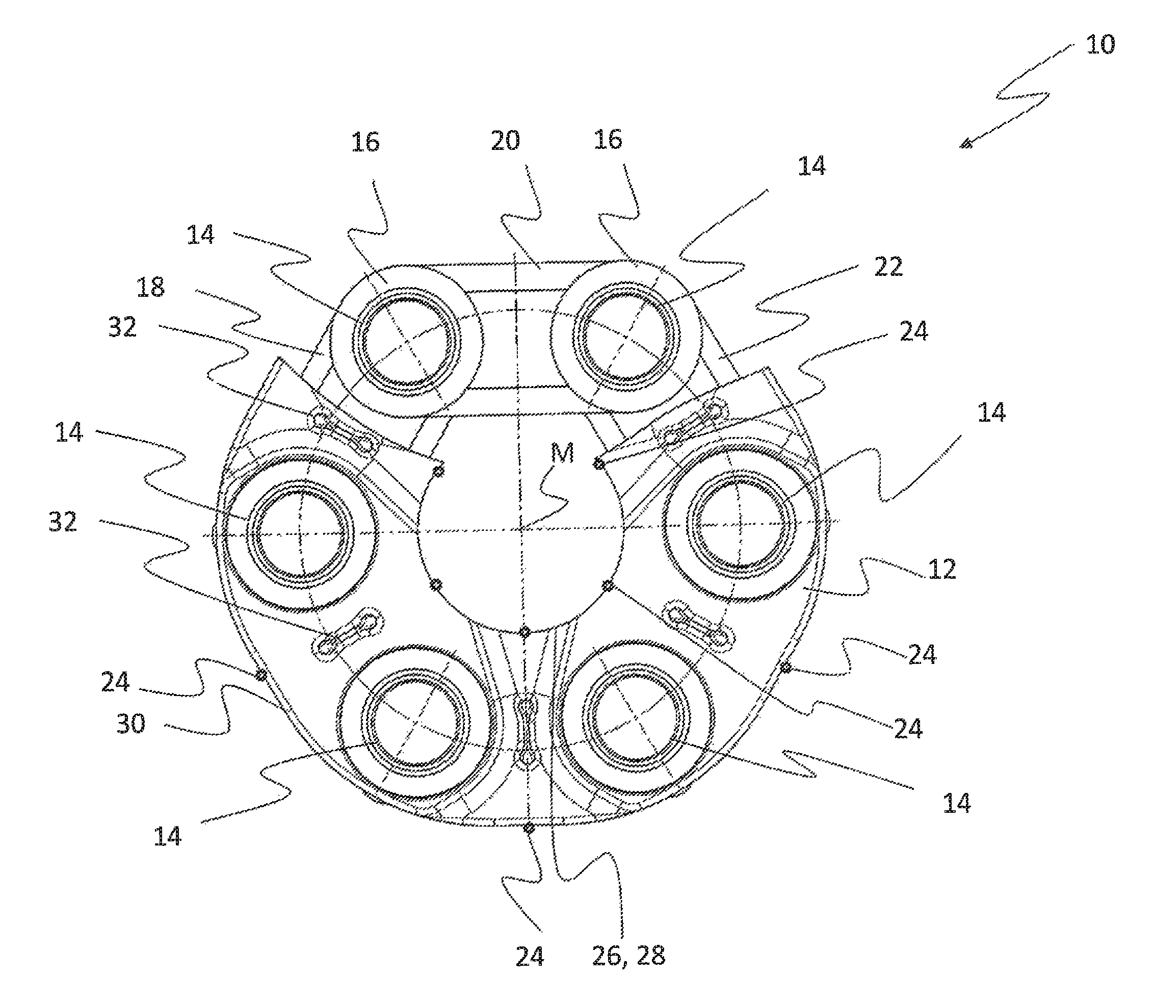
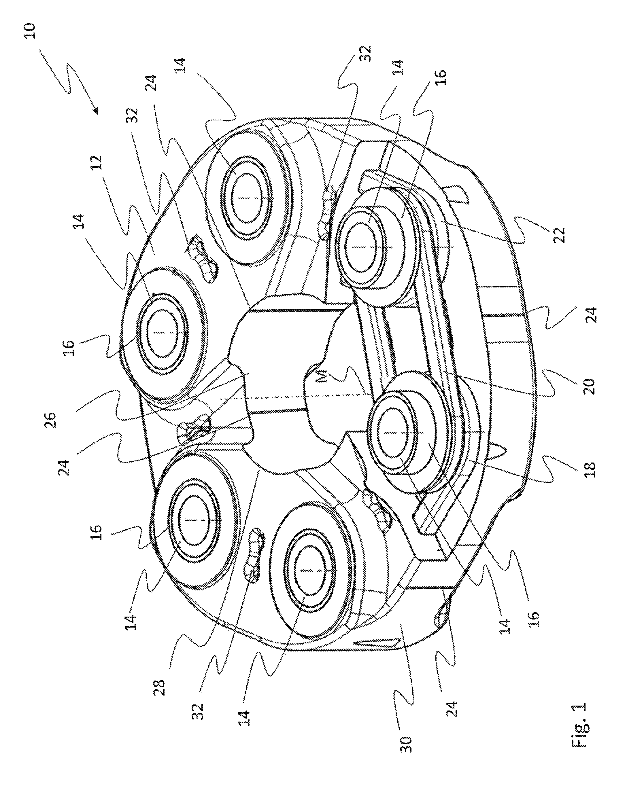
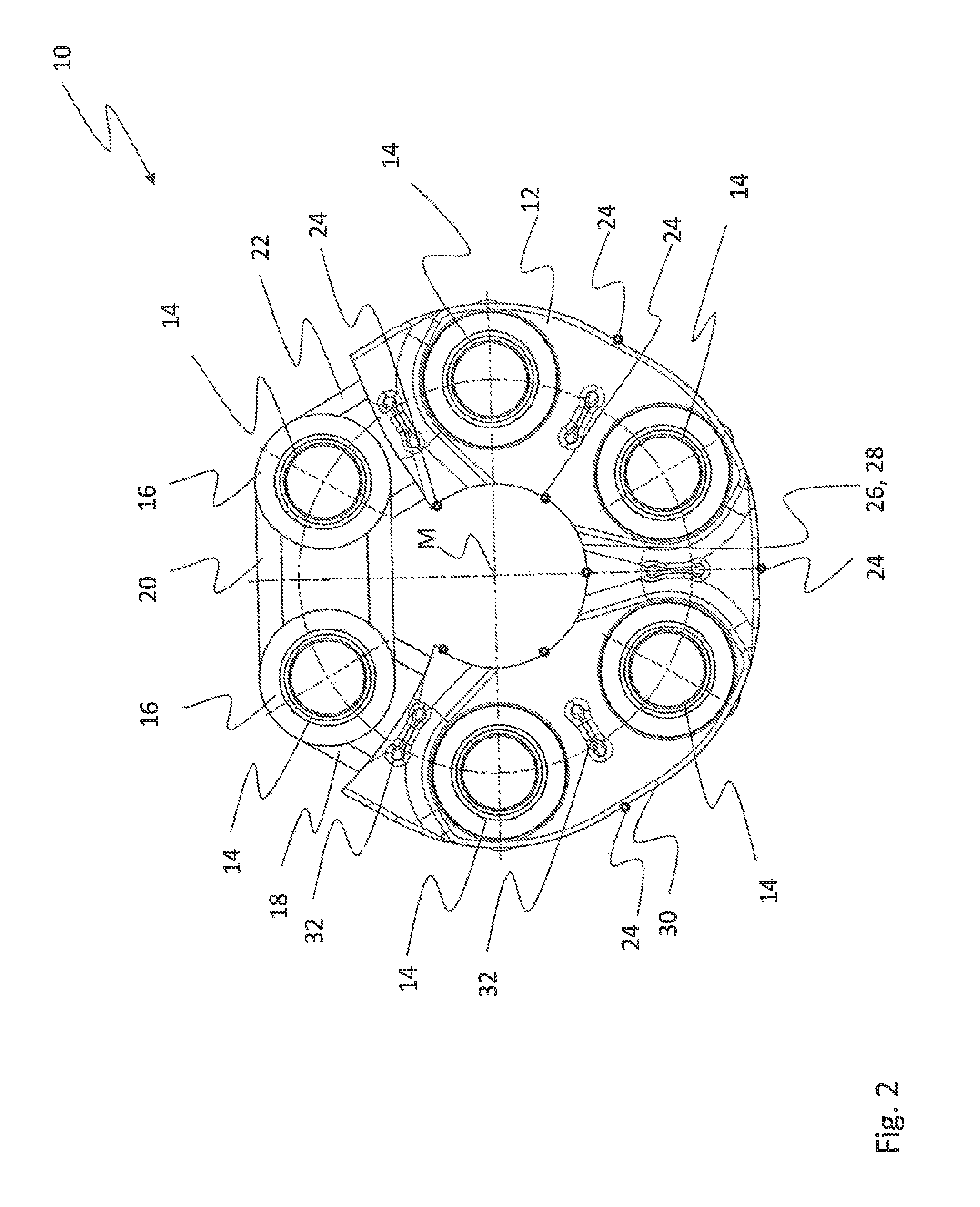
[0035]FIG. 1 shows a perspective view of the elastic joint body 10 according to the invention, with six bushes 14 which are sheathed by a rubbery-elastic sheathing 12. The bushes 14 are arranged at predetermined angular intervals on the joint body 10 in the peripheral direction with respect to a central axis M. In that region of the joint body 10 acts cording to FIG. 1 which is represented in cut-away form in the drawing, there can be seen the flange elements 16 on the bushes 14, which elements are provided for axially supporting the sets of loops 18, 20 and 22. Both the flanged bushes 16 and the sets of loops 18, 20 and 22 are sheathed by the rubbery-elastic sheathing 12.

[0036]It can also be seen from FIG. 1 that an individual bush 14 is wrapped around, in each case, by a number of sets of loops 18, 20 or 20, 22. As shown, the loop 20 wraps around two adjacent bushes 14 and loop 18 wraps around two adjacent bushes 14. Under these circumstances, provision may be made for the sets of...

second embodiment

[0043]FIG. 3 shows a perspective view of a joint body 110 according to the invention.

[0044]The joint body 110 corresponds, to a large extent, to the joint body 10 described with reference to FIGS. 1 and 2, but in the joint body 110, the gate lands 124 are arranged in line with the axes of the bushes 114.

[0045]It can also be seen in FIG. 3 that, according to this embodiment, the axial gate lands 124 span only a partial region of the axial extension of the joint body 110. Accordingly, the axial gate lands 124 do not reach as far as the edges of the joint body 110, but extend in a central region of the axial extension of the latter.

third embodiment

[0046]FIG. 4 shows a perspective view of a joint body 210 according to the invention.

[0047]The gate lands 224 of the joint body 210 extend in the peripheral direction of the latter. In this instance, the gate lands 224 run along the inner peripheral face 226 of the central aperture 228 or along the outer peripheral face 230 of the joint body 210. In other words, the gate lands 224 run completely round the inner peripheral face 226 and the outer peripheral face 230, the gate lands 224 according to this embodiment being provided in a central region of the axial extension of the joint body 210.

[0048]However, the gate lands 224 do not have to be arranged on the inner peripheral face 226 and on the outer peripheral face 230. It is sufficient if the gate lands 224 that extend in the peripheral direction are arranged either on the inner peripheral face 226 of the central aperture 228 or on the outer peripheral face 230 of the joint body 210.


PUM

PropertyMeasurementUnit
elasticaaaaaaaaaa
elastomericaaaaaaaaaa
rubbery-elasticaaaaaaaaaa

Abstract

An elastic joint body for a shaft arrangement, for the articulated connection of two shaft sections, including a plurality of bushes which are arranged at predetermined angular intervals in the peripheral direction with respect to a central axis of the joint body, a plurality of sets of loops, each set of loops wraps around two adjacent bushes, wherein the bushes and sets of loops are arranged in such a way that a central aperture which extends through the joint body in the direction of the central axis of the latter is formed in the joint body, and at least one gate land on at least one peripheral face that extends in the axial direction, and wherein the bushes and the sets of loops are sheathed, at least partially, with a rubbery-elastic sheathing, starting from the at least one gate land.

Description

TECHNICAL FIELD[0001]The present invention relates to an elastic joint body for a shaft arrangement, for the articulated connection of two shaft sections, the joint body having a plurality of bushes which are arranged at predetermined angular intervals in the peripheral direction with respect to a central axis of the joint body, and a plurality of sets of loops, wherein each of the sets of loops wraps around two adjacent bushes. The bushes and sets of loops are arranged in such a way that a central aperture which extends through the joint body in the direction of the central axis of the latter is constructed in the joint body.BACKGROUND OF RELATED ART[0002]Joint bodies of this kind, which are also often referred to as “joint discs”, are known from the prior art and are disclosed, for example, in document DE 27 05 598 A1. The joint body disclosed in that document comprises bushes which are arranged at regular angular intervals around the axis of the joint body and which are wrapped a...

Claims


Application Information

Patent Timeline
Patent Type & Authority Patents(United States)
IPC IPC(8): F16D3/62F16D3/78
CPCF16D3/78F16D3/62B29C45/00
Inventor MEMEL, KARL-HEINZHINGERL, ANTONNINDEL, WOLFGANGTIETZE, JUERGEN
Owner SGF SUDDEUTE GELENKSCHEIBENFAB
Why Eureka
Try Eureka