

Relay type energy dissipation diversion device and curved spillway diversion array construction method
A technology of diversion device and construction method, which is applied in water conservancy projects, sea area projects, coastline protection, etc., and can solve problems such as uneven lateral distribution of downstream stilling pool inflow, uneven lateral distribution of water flow, and high water level on the outer bank of the bend section , to achieve the effect of small engineering quantity, good flow state and uniform flow velocity lateral distribution
- Summary
- Abstract
- Description
- Claims
- Application Information
AI Technical Summary
Problems solved by technology
Method used
Image

Examples
Embodiment 1
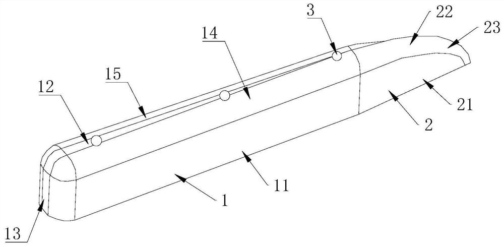
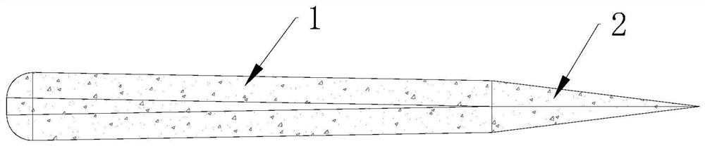
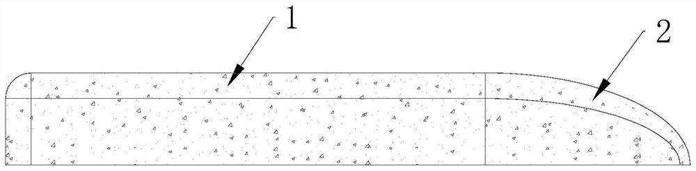
[0039] An energy dissipation guide device, such as Figure 1-3 As shown, it includes a diversion body 1 and a diversion head 2 , one end of the diversion head 2 is connected to the diversion body 1 .
[0040] The guide body 1 includes a first side plate 11 and a second side plate oppositely arranged, a first top plate 12 provided on the first side plate 11 and the second side plate, a first top plate 12 provided on the first side plate 11 and the second side plate The side plates are away from the rear cover plate 13 on one side of the head, and the first side plate 11 and the second side plate are vertically arranged.
[0041] The guide head 2 includes a vertically arranged first head side plate 21 and a second head side plate and a second top plate 22 arranged on the first head side plate 21 and the second head side plate, The end of the first head side plate 21 away from the flow guide body 1 and the end of the second head side plate away from the flow guide body 1 are clo...
Embodiment 2
[0049] A construction method for a curved spillway diversion array, such as Figure 4 As shown, it includes the following steps:
[0050] Step 1. Measure the specifications and dimensions of the spillway, including the width of the spillway, the height of the side walls, and the radius and angle of the spillway bend, determine the starting point, end point, and length of the bend, and divide the bend spillway into several sections: the upstream initial section, the middle section The curved section and the downstream section, in this embodiment, the upstream initial section has two sections, the curved section has one section, and the downstream section is divided into five sections, a total of eight groups;
[0051] Step 2. Determine the distribution of the diversion devices in the spillway, divide the forty diversion devices into eight groups, and every five diversion devices form a group, and there are 1 to 8 groups from the beginning of the bend to the downstream, and divi...
PUM
 Abstract
Description
Claims
Application Information