Elevator installation and use of such elevator installation for high-speed elevators

a high-speed elevator and installation technology, applied in elevators, mine lifts, buildings types, etc., can solve the problems of vibration and noise, deficient travel comfort of elevator installation, and unpleasant for passengers, so as to reduce problems, improve travel comfort, and avoid excessive mechanical or control complication.

Inactive Publication Date: 2010-02-23
INVENTIO AG
View PDF14 Cites 3 Cited by
  • Summary
  • Abstract
  • Description
  • Claims
  • Application Information

AI Technical Summary

Benefits of technology

[0006]The object therefore arises of providing an elevator installation which on the one hand reduces the problems arising due to the pressure shock when the counterweight and the elevator car pass and correspondingly improves travel comfort and on the other hand does not create excessive mechanical or control complication.
[0007]Moreover, solutions are to be offered which enable good space utilization of the building and are particularly suitable for use in high-speed elevators.
[0008]According to the present invention these objects are fulfilled by provision of a specially designed elevator shaft having a local cross-sectional enlargement in the region where the elevator car and the oppositely running counterweight meet in the elevator shaft. Due to such a local cross-sectional enlargement the pressure shock, which appears to be the principal cause for vibrations and noises, can be significantly reduced without the space enclosed by the elevator shaft having to be significantly increased.
[0009]Movement of the counterweight past the elevator car can take place almost free of vibration and noise through a corresponding constructional measure in creation of the elevator shaft.

Problems solved by technology

A pressure shock in the elevator shaft, which can cause vibrations and noise, can occur when the counterweight passes the elevator car particularly in single elevator shafts and with fast-moving elevator cars.
Moreover, the sudden pressure change, which is connected therewith, in the elevator car can be unpleasant for the passengers or the vibrations can be sensed as disturbing.
The elevator installation then has deficient travel comfort.
Disruptive noises can also arise in buildings in which the elevator installation is located.
These problems occur particularly with present-day elevator installations, since there is increasing effort to reduce the enclosed space as much as possible and to accommodate components of the elevator installation in the smallest possible space.
This problem of crossing of the counterweight and the elevator car in the elevator shaft has been known for a long time.
Passengers can, however, perceive this reduction in speed as unpleasant.
In addition, the conveying capacity of the overall installation is reduced, because a longer travel time results due to the reduction in speed.

Method used


Image

  • Elevator installation and use of such elevator installation for high-speed elevators
  • Elevator installation and use of such elevator installation for high-speed elevators
  • Elevator installation and use of such elevator installation for high-speed elevators

Examples


Embodiment Construction

[0017]The following detailed description and appended drawings describe and illustrate various exemplary embodiments of the invention. The description and drawings serve to enable one skilled in the art to make and use the invention, and are not intended to limit the scope of the invention in any manner. In respect of the methods disclosed, the steps presented are exemplary in nature, and thus, the order of the steps is not necessary or critical.

[0018]Components which are the same and function similarly or identically are provided in all figures with the same reference numerals.

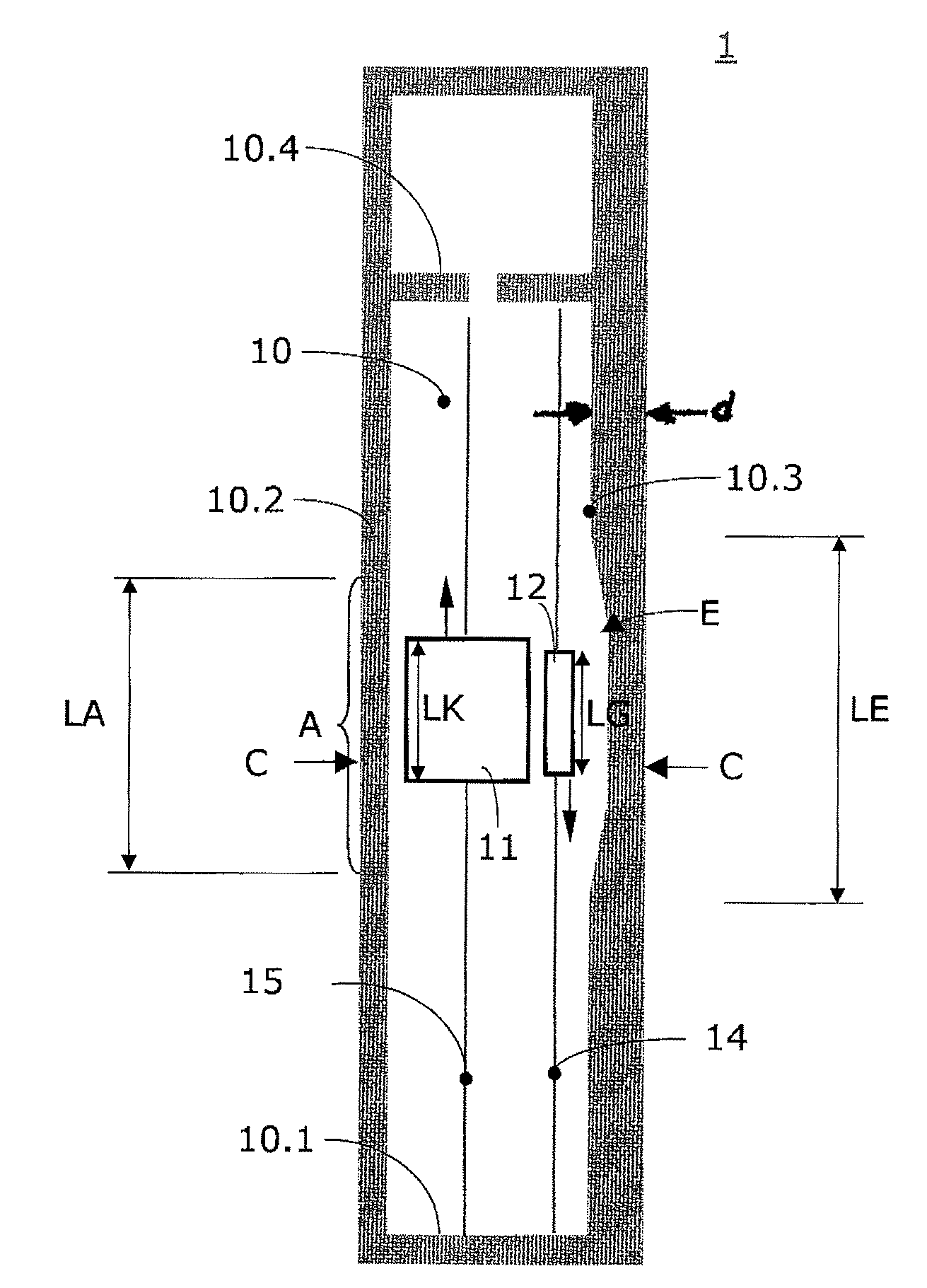
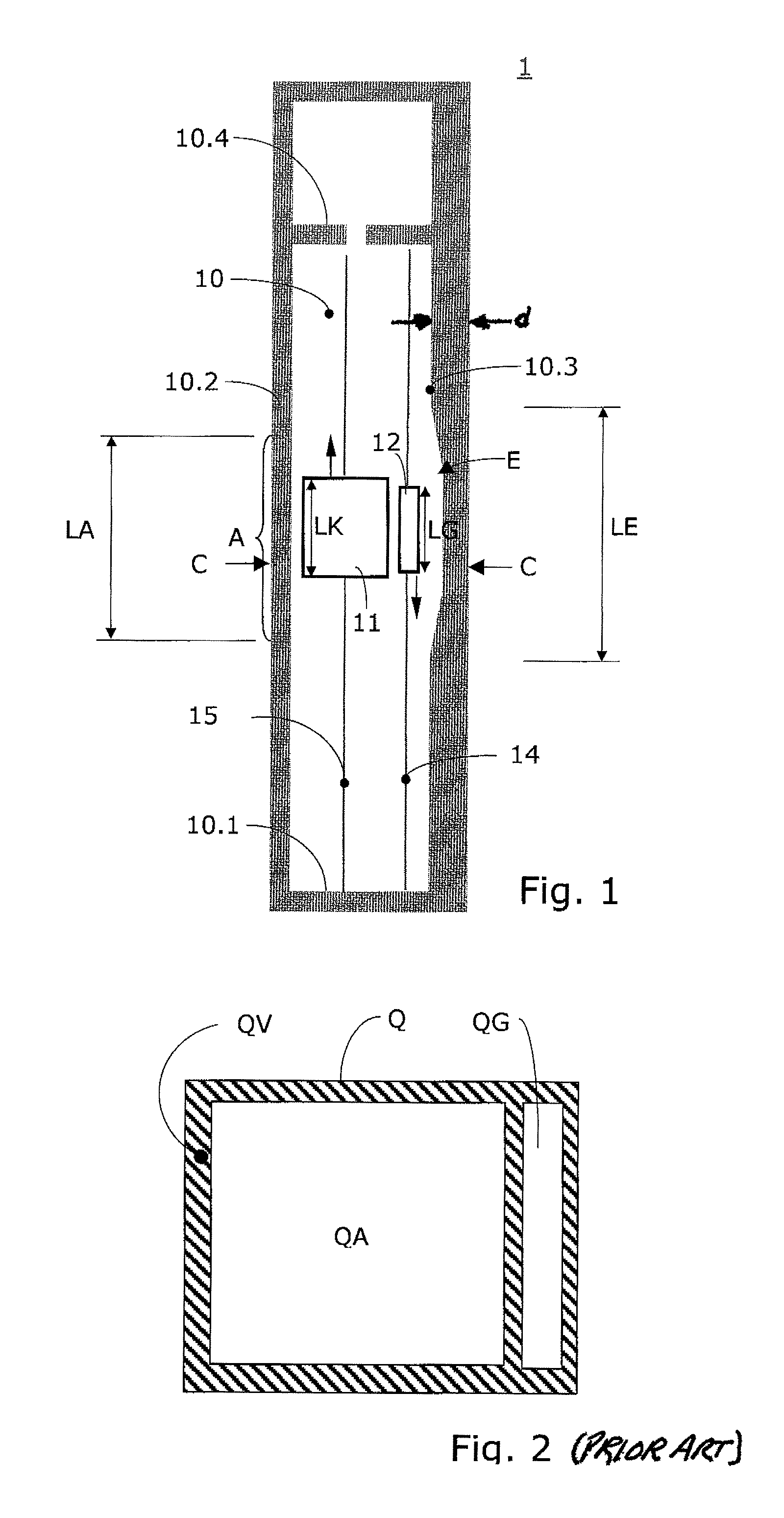
[0019]FIG. 1 shows an elevator installation 1. The elevator installation 1 comprises an elevator shaft 10 which in the illustrated example is bounded by a floor 10.1, side walls 10.2, 10.3 and a (intermediate) roof 10.4. Disposed in the elevator shaft 10 is at least one elevator car 11 and counterweight 12, which are arranged to be movable along vertical rectilinear guide tracks 14, 15. The elevator car 11 an...


PUM


Abstract

An elevator installation with an elevator shaft and an elevator car which is connected with a counterweight such that on movement of the elevator car the counterweight executes an opposite movement and the elevator car moves past the counterweight in a proximity region in the elevator shaft. Provided in the proximity region is an enlargement of the cross-section of the elevator shaft so as to reduce a pressure shock which builds up in the proximity region when the elevator car moves past the counterweight. Noise and vibrations can thereby be prevented.

Description

FIELD OF THE INVENTION[0001]The invention relates to an elevator installation with an elevator shaft, a counterweight and an elevator car wherein the elevator car moves past the counterweight in the elevator shaft, and in particular to a high-speed elevator installation of this type.BACKGROUND OF THE INVENTION[0002]In elevator installations having an elevator car connected with a counterweight by way of support means the counterweight moves in opposite direction to the elevator car. The elevator car and the counterweight are in that case respectively guided in their own substantially rectilinear guide tracks. A pressure shock in the elevator shaft, which can cause vibrations and noise, can occur when the counterweight passes the elevator car particularly in single elevator shafts and with fast-moving elevator cars. Moreover, the sudden pressure change, which is connected therewith, in the elevator car can be unpleasant for the passengers or the vibrations can be sensed as disturbing...

Claims


Application Information

Patent Timeline
Patent Type & Authority Patents(United States)
IPC IPC(8): B66B7/00B66B7/02B66B9/00
CPCB66B11/0005B66B7/00B66B7/02
Inventor KUIPERS, ERWIN
Owner INVENTIO AG
Why Eureka
Try Eureka