Thermostatic mixing valve

a technology of mixing valve and valve body, which is applied in the direction of fluid heater, non-electric variable control, instruments, etc., can solve the problems of increasing the part and production cost of the valve, complicated design of such mixing valves, and the need for additional construction features or components

Active Publication Date: 2010-02-23
GSA IND AUST
View PDF6 Cites 11 Cited by
  • Summary
  • Abstract
  • Description
  • Claims
  • Application Information

AI Technical Summary

Benefits of technology

[0008]Preferably, the second fluid seat is formed as an elongate portion extending in the direction of the movement of the piston so as to allow the piston to slide along the elongate portion to thereby allow for continued expansion of the thermostatic element.
[0014]In one preferred arrangement, a mixing tube is configured to seat a trailing end of the thermostatic element, while a leading end of the thermostatic element is arranged to contact a portion of the piston. The adjustment mechanism may include a thread arrangement formed on the periphery of the mixing tube which is arranged to engage with a thread formed in the sidewall of the mixing chamber. Such a thread arrangement enables the mixing tube's positioning within the mixing chamber to be adjusted relative to the piston by rotating the mixing tube.
[0015]Alternatively, the adjustment mechanism may enable the size of the mixing tube to be varied so that it can be located in one of a series of seats formed in the sidewall of the mixing chamber.

Problems solved by technology

However, the design of such mixing valves has been complicated by the need to provide a mechanism for allowing for any continued expansion of the thermostatic element after the flow of hot and cold fluids is adjusted.
The inclusion of such an arrangement requires an extra opening to be formed in the valve body and also increases the part and production costs for the valve.
Another problem with such mixing valves is that to enable adjustment of the set temperature of the mixed water exiting the outlet (and thereby the rest position of the thermostatic element), additional constructional features or components have to be provided.
This inevitably increases the cost of the mixing valve.

Method used


Image

  • Thermostatic mixing valve
  • Thermostatic mixing valve
  • Thermostatic mixing valve

Examples


Embodiment Construction

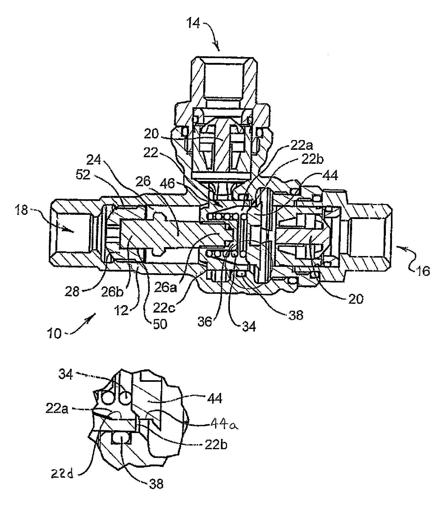
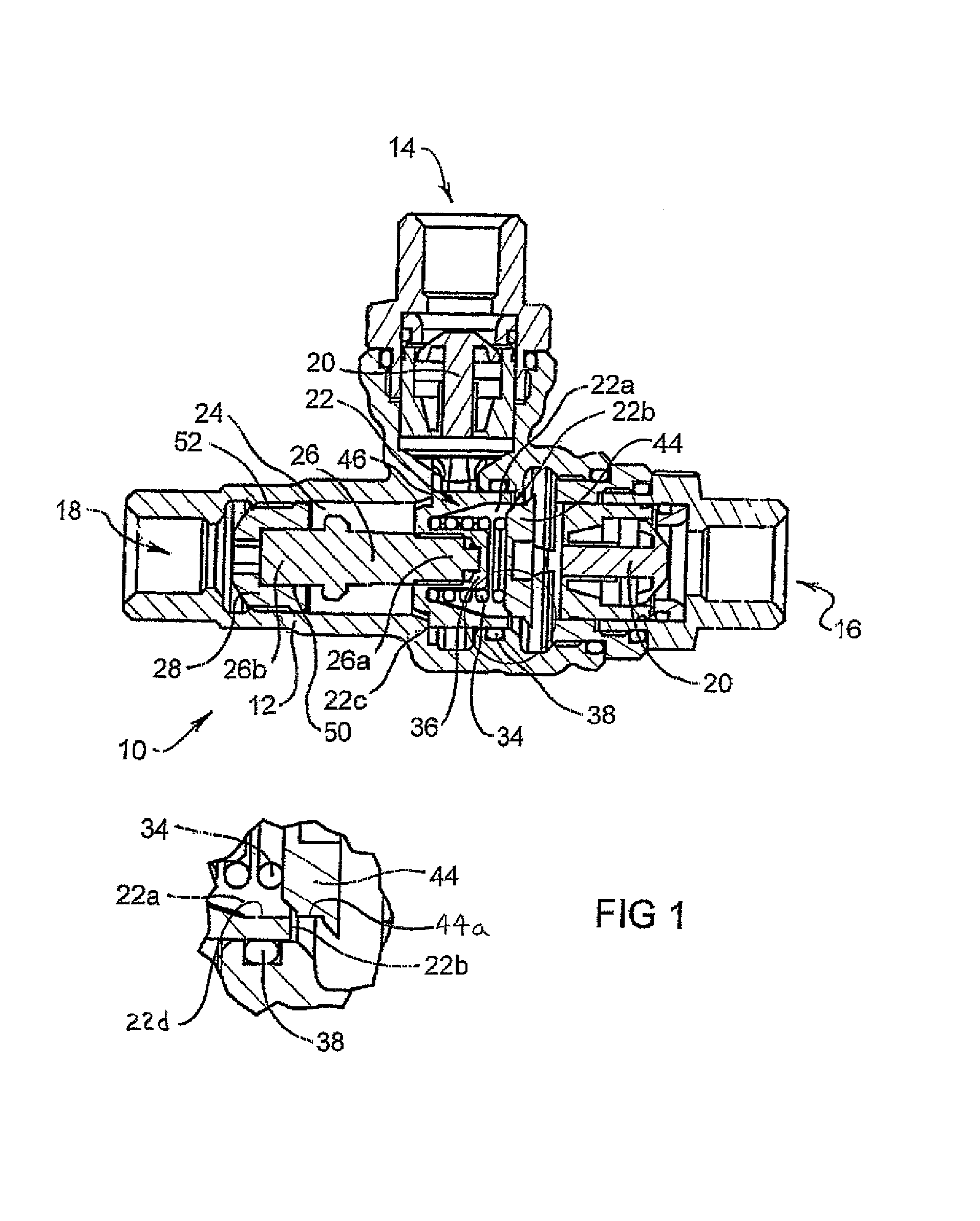
[0027]FIG. 1 illustrates a thermostatic mixing valve 10 in accordance with an embodiment of the invention. The valve 10 includes a valve body 12, a cold fluid inlet 14, a hot fluid inlet 16 and a mixed fluid outlet 18. As is evident from FIG. 1, the cold fluid inlet 14 and the hot fluid inlet 16 are orientated in an “L” shape so that the cold and hot fluid inlets 14, 16 are orientated at right angles to each other.

[0028]Located within the valve body 12 adjacent to each of the cold and hot fluid inlets 14, 16 is a respective check valve 20. Each check valve 20 is arranged to prevent inadvertent backflow of fluid through the respective cold and hot inlets 14, 16. It will be appreciated that although it is desirable to include such a check valve 20 adjacent each of the cold and hot inlets 14, 16 it is not essential to a proper working of the thermostatic mixing valve 10.

[0029]Located between the respective cold and hot fluid inlets 14, 16 is a regulating piston 22. The piston 22 is loc...


PUM


Abstract

Thermostatic mixing valve has a valve body, a cold fluid inlet, a hot fluid inlet, and a fluid outlet. Mixing chamber is located between the respective fluid inlets and the fluid outlet. Thermostatic element is located in or adjacent to the mixing chamber and is arranged to contact a piston at one end and via a mixing tube the valve body at the other end. Piston regulates flow through the fluid inlets into the mixing chamber. The piston is can move due to continued expansion of the thermostatic element after the piston has closed off the second fluid inlet. Valve body has an internal thread with which a thread on mixing tube permits adjustment of the relative position of the thermostatic element within the valve body and hence the set temperature of the thermostatic mixing valve.

Description

CROSS-REFERENCE TO RELATED APPLICATION[0001]This is a continuation-in-part application that claims benefit, under 35 USC §120, of co-pending International Application PCT / AU2004 / 000748 filed on 4 Jun. 2004, designating the United States, which claims foreign priority benefits under 35 USC §119 (a) to Australian Patent Application No. 2003902843, filed 6 Jun. 2003, which applications are incorporated herein by reference.FIELD OF THE INVENTION[0002]The present invention relates to a thermostatic mixing valve.BACKGROUND OF THE INVENTION[0003]Thermostatic mixing valves enable hot and cold fluids, typically water, to be accurately mixed so as to deliver fluid at a desired temperature to the valve outlet. One form of thermostatic mixing valves adopts a “T” pattern in which the hot and cold water enters through inlets in the arms of the “T” and the mixed water exits through an outlet in the base of the “T”. Another form of thermostatic mixing valve adopts an “L” pattern in which the hot an...

Claims


Application Information

Patent Timeline
Patent Type & Authority Patents(United States)
IPC IPC(8): G05D23/185F23N5/10G05D23/08G05D23/12G05D23/13
CPCG05D23/134
Inventor CUNNINGHAM, AARON CHRISTIANSCOTT, TONY MARK
Owner GSA IND AUST
Why Eureka
Try Eureka