Control arm, and method of making a control arm

a control arm and control arm technology, applied in the field of control arms, can solve the problems of increasing the weight of the mounting eye, the structure of the control arm of aluminum is generally more complex than that of the control arm, and the press fitting process is rather complicated and time-consuming, so as to prevent the damage to the rubber-metal elements, reduce the weight, and ensure the effect of precision

Inactive Publication Date: 2005-07-05
BENTELER AUTOMOBILTECHNIK GMBH
View PDF4 Cites 15 Cited by
  • Summary
  • Abstract
  • Description
  • Claims
  • Application Information

AI Technical Summary

Benefits of technology

[0014]As a consequence of the fixed positioning of the connection tube and the mounting eyes during friction welding only little heat is introduced into sleeve blanks with vulcanized rubber-metal elements. Thus, damage to the rubber-metal elements is prevented, while realizing a homogenous fine-grained joint. The need for a press-fitting securement of rubber-metal elements is eliminated in view of their direct vulcanization into the sleeve blanks. Also, there is no need for any after-treatments, as required in prior art approaches that involve precise finishing steps of inner surfaces of the sleeve blanks as well as outer surface of bushings of separately produced rubber-metal bearings to provide precise tolerances during press-fitting. The absence of any bushings not only reduces weight but eliminates working steps to thereby reduce the fabrication costs.
[0015]Calibration through cold upsetting of joined components ensures precisely defined distance tolerance between the axes of the rubber-metal elements. Subsequently, the joints can be smoothed circumferentially, e.g. by a material removing process or rolling process.
[0016]Since the connection tube and the sleeve blanks are held in a single restraint during treatment, welding and, optional, calibration, the control arm can be produced not only in a precise and accurate manner for use in an undercarriage of a motor vehicle but can be produced on a large scale with reproducible results. Any possibility of misalignment is eliminated.

Problems solved by technology

Press-fitting constitutes a rather complicated and time-consuming process.
Control arms of aluminum are generally more complex in structure than control arms made of steel.
Also, the provision of an outer bushing for the bearing element increases the weight of the mounting eye.
As a consequence, there is an increase of unsprung masses in an axle system.
This may adversely affect the driving comfort of a motor vehicle.
This welding process is fairly complicated, when round parts are involved.
Moreover, friction stir welding has deficiencies relating to the presence of a hole at the end of the welding process, when the pin-shaped probe is removed.
This hole is exposed to increased corrosive stress and significant notch effect, when the control arm is used in an undercarriage.
As a consequence, the service life of the control arm is adversely affected.
However, connection of a thin-walled tube to a large-area block surface poses many problems and results in a significantly increased notch effect.
Thus, the life of such a connection is limited so that this type of connection is effectively unsuitable for use in chassis engineering, and moreover the overall weight of the component is also increased.

Method used


Image

  • Control arm, and method of making a control arm
  • Control arm, and method of making a control arm
  • Control arm, and method of making a control arm

Examples


first embodiment

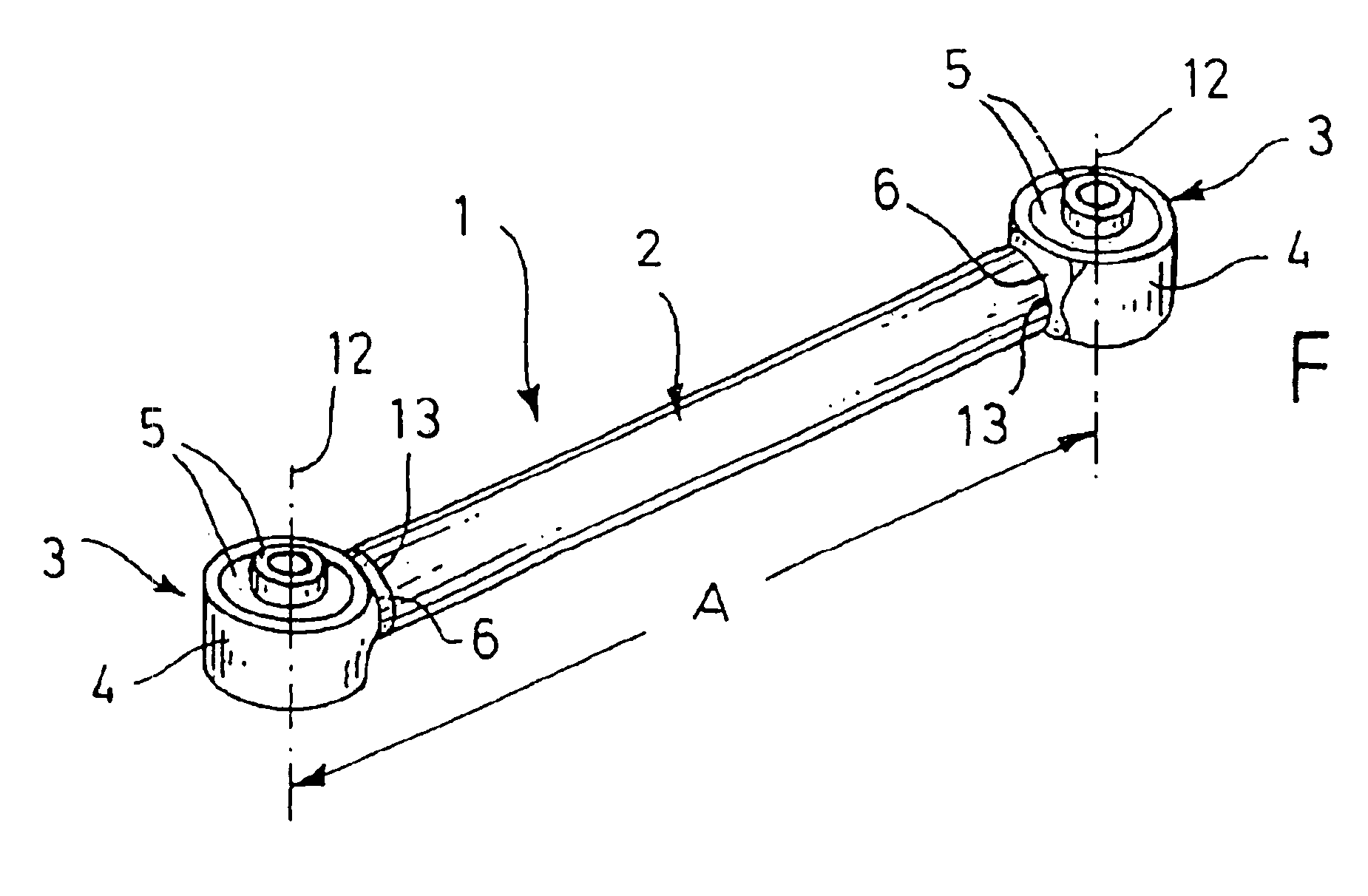
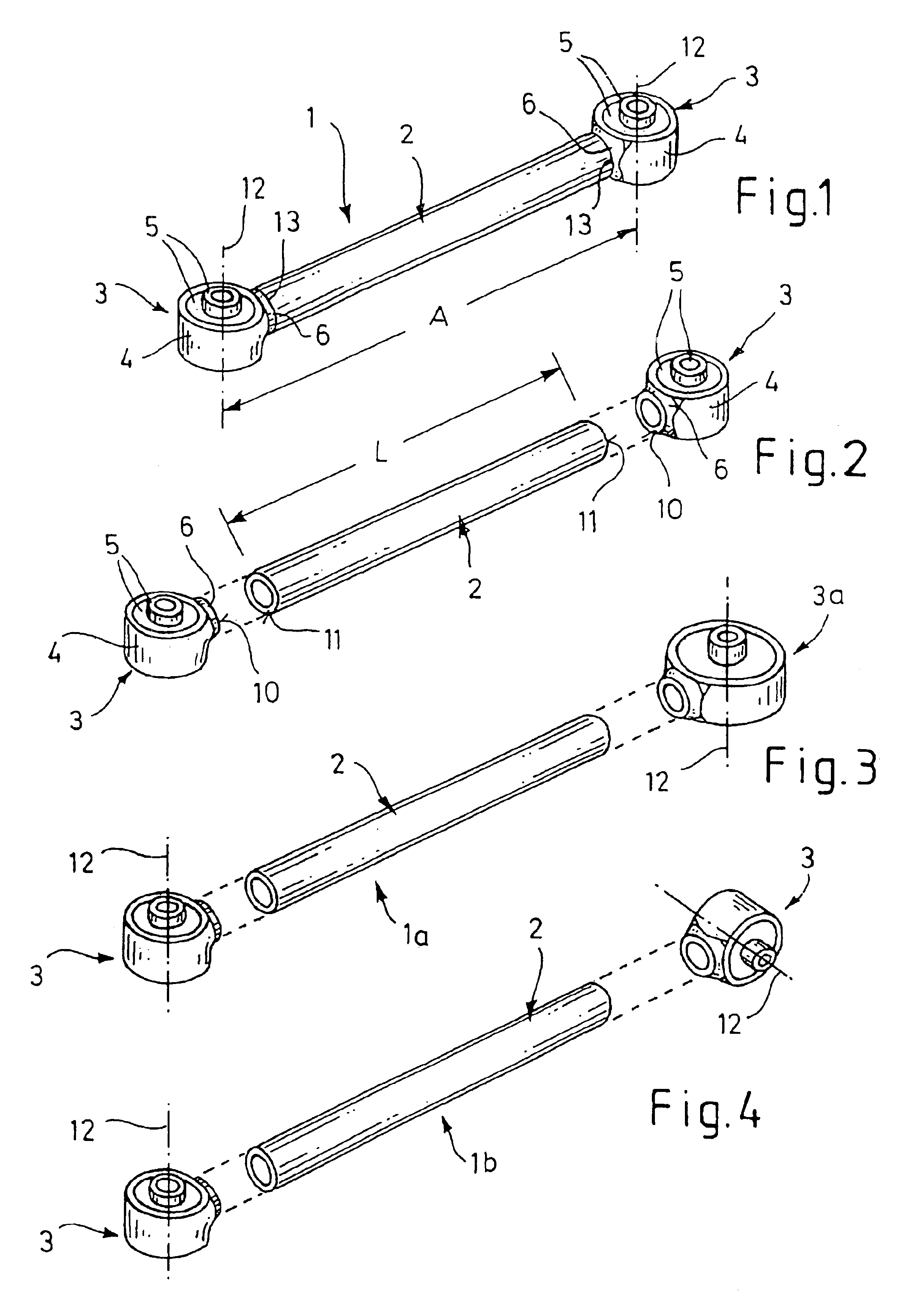
[0030]Turning now to the drawing, and in particular to FIG. 1, there is shown a perspective view of a control arm according to the present invention, generally designated by reference numeral 1, for use in an undercarriage of a motor vehicle. The control arm 1 includes a straight connection tube 2 made of light metal alloy or plastic. Currently preferred is an aluminum alloy containing, by weight percent, Si 0.59-0.81%, Mn 0.28-0.38%, Mg 0.22-0.30%, Fe 0.16-0.22%, the balance Al and incidental impurities during fusion welding. A particular example of an aluminum alloy includes, by weight percent, Si 0.69%, Mn 0.33%, Mg 0.26%, Fe 0.20%, the balance Al and incidental impurities during fusion welding.

[0031]The connection tube 2 has opposite ends, each end joined by friction welding to a mounting eye, generally designated by reference numeral 3. Each mounting eye 3 includes a sleeve 4, which is provided with a protruding collar 6, and a rubber-metal element 5 which is vulcanized into th...

second embodiment

[0036]FIG. 3 shows an exploded view of a control arm according to the present invention, generally designated by reference numeral 1a. Parts corresponding with those in FIG. 1 are denoted by identical reference numerals and not explained again. In this embodiment, the control arm 1a is provided with mounting eyes 3, 3a of different size, whereby the axes 12 of the mounting eyes 3, 3a are oriented in parallel relationship. Production and joining of the individual components of the control arm 1a correspond to the production and joining as described in connection with FIGS. 1 and 2, so that a further description thereof is omitted for the sake of simplicity.

third embodiment

[0037]FIG. 4 is an exploded view of a control arm according to the present invention, generally designated by reference numeral 1b. Parts corresponding with those in FIG. 1 are denoted by identical reference numerals and not explained again. In this embodiment, the control arm 1b is provided with mounting eyes 3 of same size and having axes 12 which are offset to one another by 90°, i.e. they are oriented perpendicular to one another. Production and joining of the individual components of the control arm 1b correspond to the production and joining as described in connection with FIGS. 1 and 2, so that a further description thereof is omitted for the sake of simplicity.

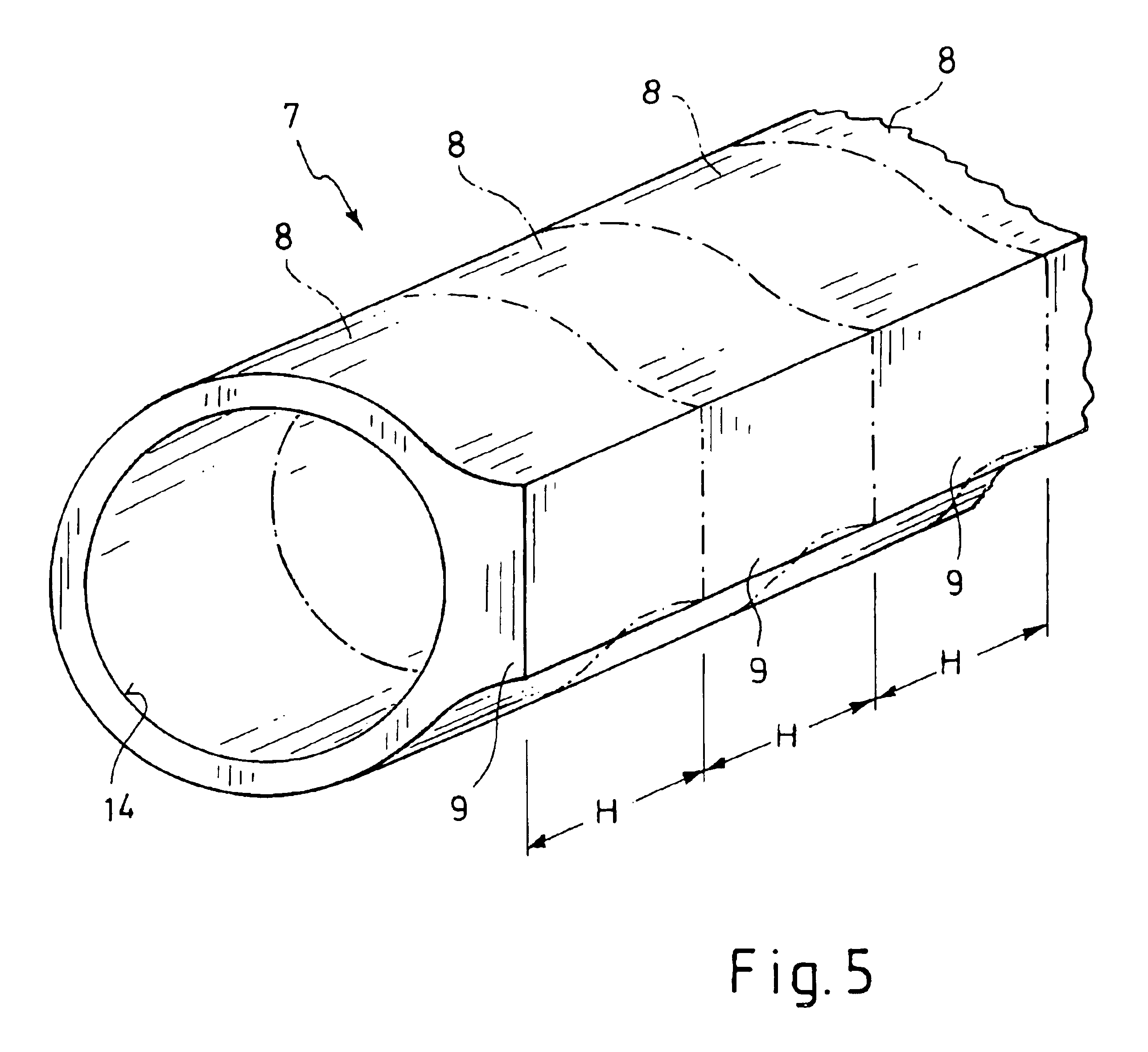
[0038]Turning now to FIG. 8, there is shown a perspective illustration of a mounting eye 3b which, unlike the mounting eyes 3, 3a, has an oval or approximate rectangular configuration. The advantage hereby is the fact that any desired cross section can be made in the profile and vulcanized subsequently. Thus, the rubbe...


PUM

PropertyMeasurementUnit
weight percentaaaaaaaaaa

Abstract

A control arm includes a connection tube and two mounting eyes respectively attached to opposite ends of the tube. Each mounting eye has a sleeve and a rubber-metal element vulcanized into the sleeve. In a method of making such a control arm, an elongate tubular member is sized to a sleeve blank of a length commensurate with the tube. Parallel thereto, an extruded profile is made with a cross sectional configuration of the sleeve and subsequently sized to the axial height of the sleeve. Rubber-metal elements are vulcanized into the sleeve blanks which together with the tube are then clamped, axially shiftable, in a friction welding machine for subsequently fabricating protruding collars on the sleeves through material removal and joining the end surfaces of the protruding collars with the end surfaces of the tube. While still clamped, the tube and the mounting eyes are calibrated through cold upsetting and the joints are smoothed.

Description

CROSS-REFERENCES TO RELATED APPLICATIONS[0001]This application claims the priority of German Patent Applications, Serial Nos. 101 59 524.7, filed Dec. 5, 2001, and 102 55 049.2, filed Nov. 26, 2002, pursuant to 35 U.S.C. 119(a)-(d), the disclosure of which is incorporated herein by reference.BACKGROUND OF THE INVENTION[0002]The present invention relates, in general, to a control arm, and to a method of making such a control arm, in particular for use in an undercarriage of a motor vehicle.[0003]German patent publication DE 199 11 121 A1 describes a control arm for use in the undercarriage of a motor vehicle. The control arm includes a connection tube made of an aluminum alloy and having opposite ends formed with mounting eyes. Each mounting eye is composed of a sleeve, which is made of an aluminum alloy and formed with a protruding collar, and a bearing element, which is embedded in the sleeve. The bearing element is made as metallic bushing which includes a rubber element and is pr...

Claims


Application Information

Patent Timeline
Patent Type & Authority Patents(United States)
IPC IPC(8): B60G7/00F16F1/38
CPCB60G7/001F16F1/3842B60G2204/41B60G2206/11Y10T29/49B60G2206/82013B60G2206/8105
Inventor DRABON, RODSCHAROSE, LEONHARDKORINTH, HENDRIKNEUMANN, HANS-JURGEN
Owner BENTELER AUTOMOBILTECHNIK GMBH
Why Eureka
Try Eureka