Hydraulic unit

a technology of hydraulic units and hydraulic components, applied in the direction of positive displacement liquid engines, liquid fuel engines, braking systems, etc., can solve the problems of limiting the possible volume of damping devices, the structural size of the hydraulic unit is not large enough, and the hydraulic unit requires a relatively large installation space, so as to improve the production cost and adaptability of the hydraulic unit, the structural volume of the hydraulic unit is large, and the operation noise is not large. , to achieve the effect of improving the production cos

Active Publication Date: 2005-03-22
ROBERT BOSCH GMBH
View PDF7 Cites 14 Cited by
  • Summary
  • Abstract
  • Description
  • Claims
  • Application Information

AI Technical Summary

Benefits of technology

It is accordingly the object of the present invention to improve the known hydraulic units in terms of their operating noise, their structural volume, and the effort and expense of metal-cutting, and thus to improve both their production costs and their adaptability to various types of vehicle.
Compared to the hydraulic units known from the prior art cited, a hydraulic unit according to the invention has the advantage that, with unaltered compact dimensions, it includes damping devices for damping the pressure pulsations generated by the pump elements and is especially simple to produce technically. The pressure fluid conduits for hydraulically contacting the damping devices are relatively short and as a result entail little expense for metal-cutting. The idle volume, the hydraulic rigidity, and hence the controllability of the brake system are thus improved. Moreover, the volume of the damping device can be easily adapted to a given specific application, since only a fractional volume is accommodated in the housing block of the hydraulic unit, while a second fractional volume, which is easily varied in size, extends outside the housing block. It is especially advantageous if the damping device protrudes with its second fractional volume into the interior of a mountable control unit, since as a result the emission of sound caused by the pressure pulsations is additionally damped.
Further advantages or advantageous refinements of the invention are disclosed. According to one feature the inlet is especially reliably sealed off from the outlet of the damping device, since the sealing point is formed by the outer contour of the pump elements in cooperation with the wall of the installation chamber of the pump elements. The sealing point is created simultaneously with the assembly of the pump elements and does not require any separate sealing elements. Hence the sealing point is not subjected to wear associated with the operating time, and at the same time costs for keeping required parts on hand and for assembly are reduced.

Problems solved by technology

This limits the possible volume of the damping devices and / or means that the hydraulic unit requires a relatively large installation space.
Moreover, the pressure fluid conduits in the hydraulic unit that are required for hydraulically connecting the damping devices can be attained only with great effort in terms of production, and because of their length they further contribute to increasing the structural size of the hydraulic unit.
Especially the maximum possible volume of the damping devices is severely restricted, since the pump elements already occupy a substantial proportion of the possible length of the housing block in the direction of the longitudinal axes of the pump elements.

Method used


Image

  • Hydraulic unit
  • Hydraulic unit
  • Hydraulic unit

Examples


Embodiment Construction

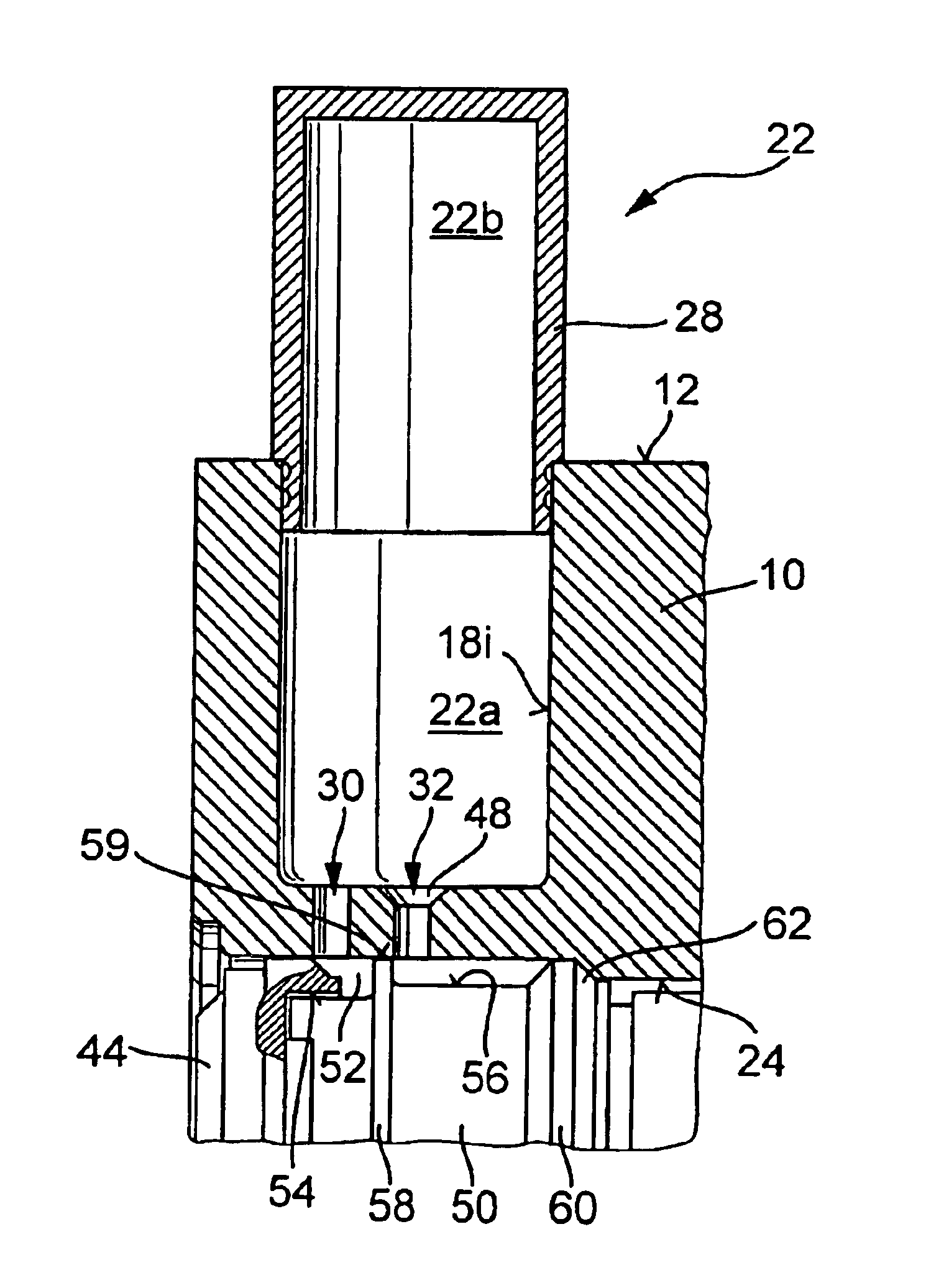
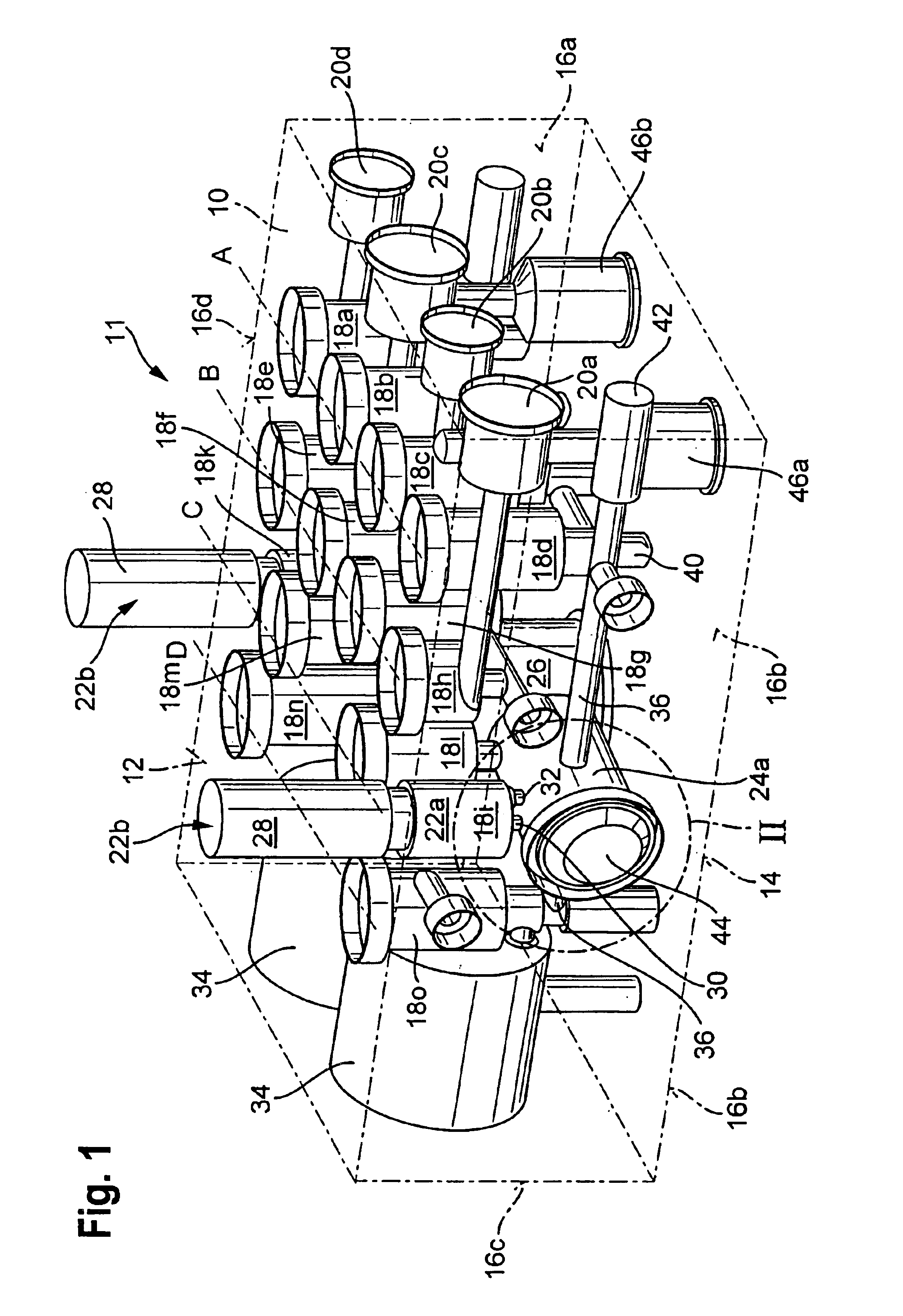
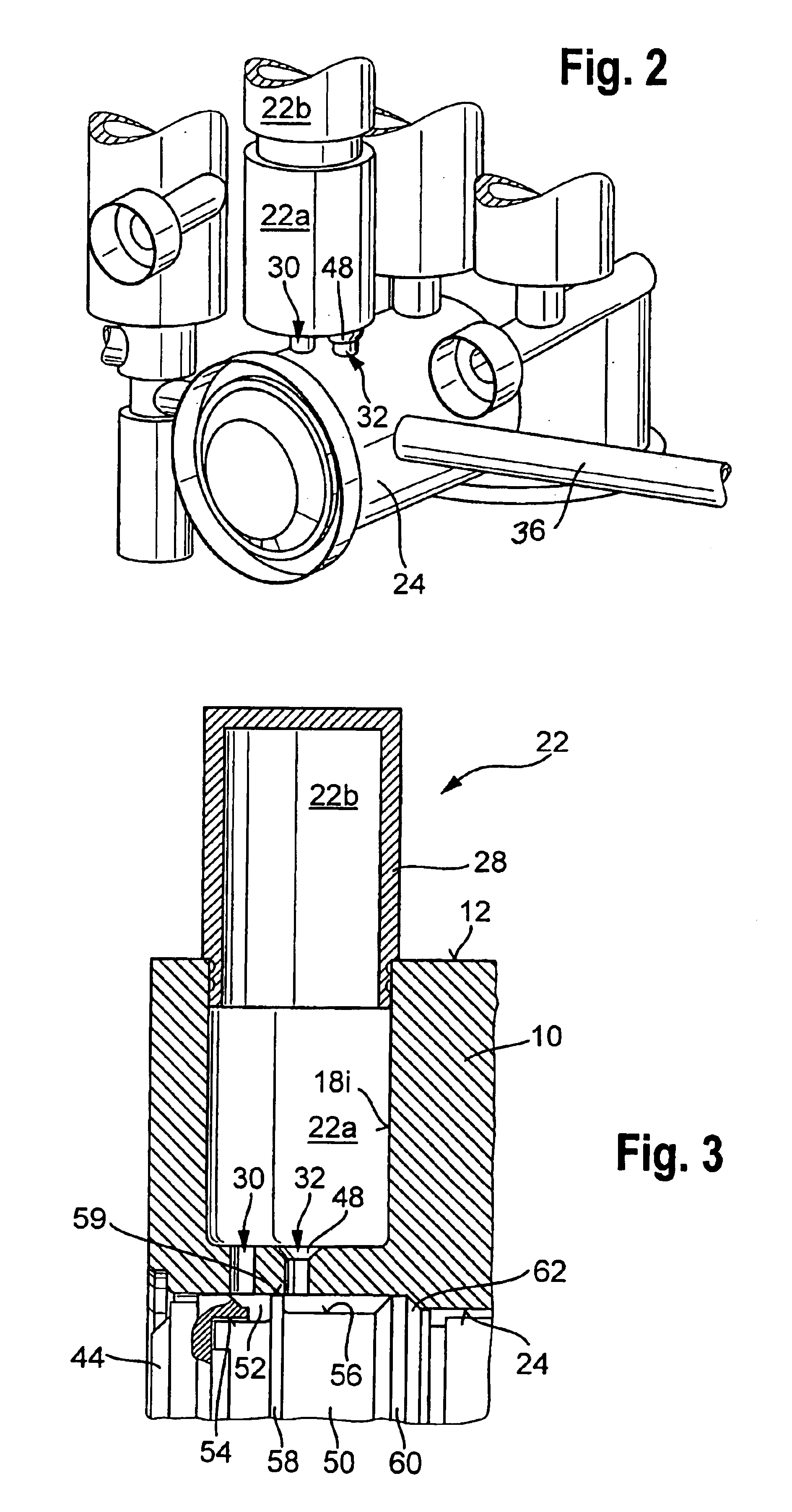
The housing block 10 of a hydraulic unit 11, shown as an example in FIG. 1, is intended for use in an anti-lock brake system with VDC (vehicle dynamics control). It comprises a parallelepiped block of nonferrous material, for instance an aluminum alloy, preferably produced by extrusion and then machined by metal-cutting. The housing block 10 has a rectangular upper mounting face 12, opposite it a lower mounting face 14, and a total of four circumferential faces 16a-d, which are oriented perpendicular to the mounting faces 12, 14. The upper mounting face 12 is intended for anchoring an electronic control unit, not shown, while an electric motor can be flanged to the lower mounting face 14. From the upper mounting face 12, installation chambers 18 embodied in cup-shaped fashion extend into the housing block 10. The installation chambers 18 essentially serve to receive magnet valves, but the magnet valves have not been shown in FIG. 1 for the sake of simplicity. A total of fourteen ins...


PUM


Abstract

A hydraulic unit for an electronically controllable brake system of a vehicle includes a housing block with mounting faces for instance for an electric motor and an electronic control unit; a plurality of connections for hydraulically contacting the block; and installation chambers, for pump elements, valves, and damping devices. These damping devices are connected hydraulically downstream to the pump elements, in order to damp operation-caused pressure pulsations and noises. Installation chambers (18i-k) for the damping devices and the installation chambers (18a-h) of the valves extend to a common mounting face of the housing block intended for mounting the electronic control unit. The damping devices protrude past this mounting face.

Description

BACKGROUND OF THE INVENTION1. Field of the InventionThe invention is directed to an improved hydraulic unit for an electronically controllable brake system of a vehicle.2. Description of the Prior ArtA housing block of a hydraulic unit of the type with which this invention is concerned is already known, for instance from German Patent Disclosure DE 198 05 843 A1. This housing block has a plurality of mounting faces, to which an electric motor, for instance, for driving pump elements disposed in the housing block, or an electronic control unit for triggering magnet valves provided in the housing block, can be secured. The housing block is furthermore provided with connections for supplying it with pressure fluid and, in addition to the installation chambers for the aforementioned pump drive, the pump elements and the magnet valves, it has still further installation chambers for damping devices. These damping devices are disposed downstream of the pump elements in terms of circuitry, ...

Claims


Application Information

Patent Timeline
Patent Type & Authority Patents(United States)
IPC IPC(8): B60T8/40B60T8/36F04B53/16F04B53/00F15B13/00F04B11/00B60T15/00F15B13/08
CPCB60T8/368B60T8/4068F04B11/0008F04B53/16F15B13/0842F15B13/086F15B13/0889F15B13/0892F15B13/0807Y10S303/10B60T15/00
Inventor WEH, ANDREASIDEGUCHI, TOMOYAMCCORMICK, NATHANPATTERSON, DOUGLAS
Owner ROBERT BOSCH GMBH
Why Eureka
Try Eureka