Suspension assembly having an integrated stable storage platform

a suspension system and storage platform technology, applied in the direction of transportation items, cycles, loading/unloading vehicle arrangment, etc., can solve the problems of light and nimble tilting mass, and achieve the effect of lowering the center of gravity and enhancing the stability of the vehicl

Active Publication Date: 2010-02-23
SWAY MOTORSPORTS INC
View PDF22 Cites 31 Cited by
  • Summary
  • Abstract
  • Description
  • Claims
  • Application Information

AI Technical Summary

Benefits of technology

[0007]In this regard, the present invention provides a suspension system for a wheeled vehicle is provided that allows for the vehicle body to be tilted by the operator in a manner that greatly enhances the stability of the vehicle while producing a fun vehicle to operate. Further, the bottom member of the suspension system is structured in a manner that provides storage capacity for installation of heavy items such as battery banks in order to preserve a lowered center of gravity for the vehicle. In the preferred embodiment, the present invention will be described in the context of a three-wheeled vehicle having a single rear drive tire and two forward wheels, although it should be appreciated by one skilled in the art that the teachings of the present invention apply equally to a four wheeled vehicle as will be described in further detail below as well as to water craft operating on pontoons or snow vehicles operating on skis.
[0008]The basic principal of the present invention is to provide a pivoting vehicle wherein a vertical axis of the vehicle and a vertical set of axes running through each of two spaced tires remains parallel as the vehicle tilts and wherein the user's legs control the tilt of the vehicle. It should be appreciated that a number of mechanical methods exist that provide this desired result. The important inventive concept is that the chassis is connected to at least two wheels that tilt as the chassis tilts so that these elements remain in their parallel orientation and that the control of the tilt of the chassis is accomplished through the use of the riders legs directly on the linkage itself. Further, to enhance the stability of the vehicle the bottom suspension member is expanded to include storage therein for placement of heavy load items.
[0009]The present invention is implemented preferably using a four bar suspension. The four bars that make up the suspension are arranged in a parallelogram shape wherein two suspension members are parallel to one another along the top and bottom of the suspension arrangement and two bars are substantially parallel to one another along the left and right sides of the suspension arrangement. The ends of each of the suspension members are pivotally attached to one another to form a hinged parallelogram. The hinged parallelogram is then affixed to the chassis of the vehicle by pivotally attaching both the top and bottom bars to the vehicle chassis at approximately their mid points. The bottom suspension member preferably includes a structural strut that extends between the left and right vertical bars while further extending rearward from the strut and including a storage compartment therein. In this manner, the storage compartment provides a location for the placement of batteries that power the vehicle in a relatively low position within the vehicle to enhance the stability and lower the center of gravity. In particular, since the bottom platform does not tilt as it is affixed to the bottom bar of the suspension the weight of the batteries is removed from the tilting aspects of the linkage. As a result the tilting mass remains light and nimble. This allows the vehicle to have lightweight handling response and overall feel while still carrying a substantial battery load.
[0010]Accordingly, it is an object of the present invention to provide a suspension system for a tilting vehicle that allows the forces generated by the vehicle to be transferred using a center of effort that is directed perpendicular to the traction surfaces of the tires. Further, it is an object of the present invention to provide a suspension system for a tilting vehicle that provides a storage position at the lowest possible position within the vehicle for storage of heavy items such as large battery banks thereby lowering the center of gravity of the vehicle while also removing the weight of the load from the tilting assembly. Finally, it is an object of the present invention to provide a suspension system for a tilting vehicle that both facilitates a low center of gravity arrangement by placing heavy load storage in a lowered position while also still allowing active tilt control by the vehicle operator in a manner that greatly reduces the complexity of the system and the need for multiple sensors, hydraulic arrays and substantial computer power.

Problems solved by technology

As a result the tilting mass remains light and nimble.

Method used


Image

  • Suspension assembly having an integrated stable storage platform
  • Suspension assembly having an integrated stable storage platform
  • Suspension assembly having an integrated stable storage platform

Examples


Embodiment Construction

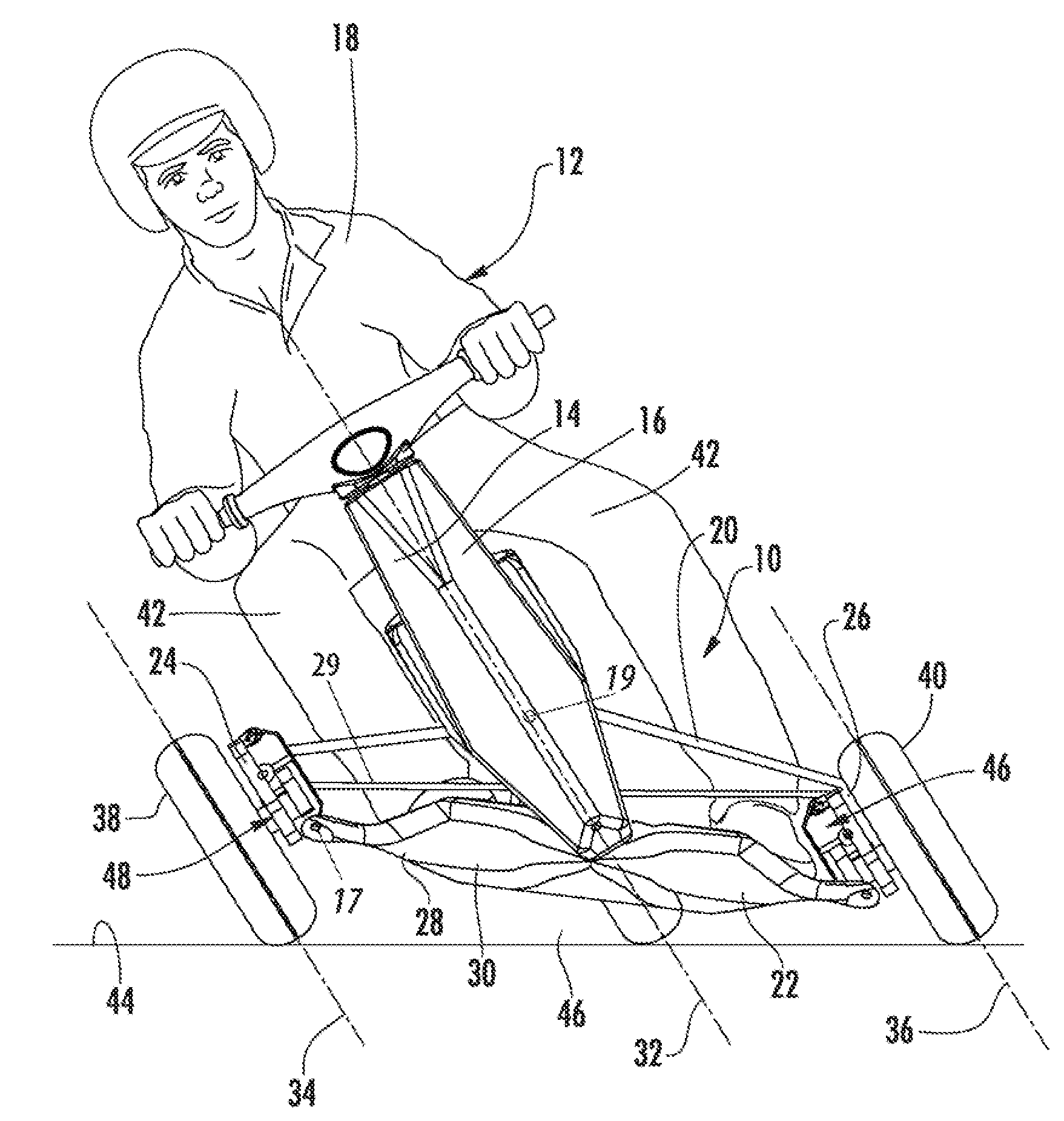
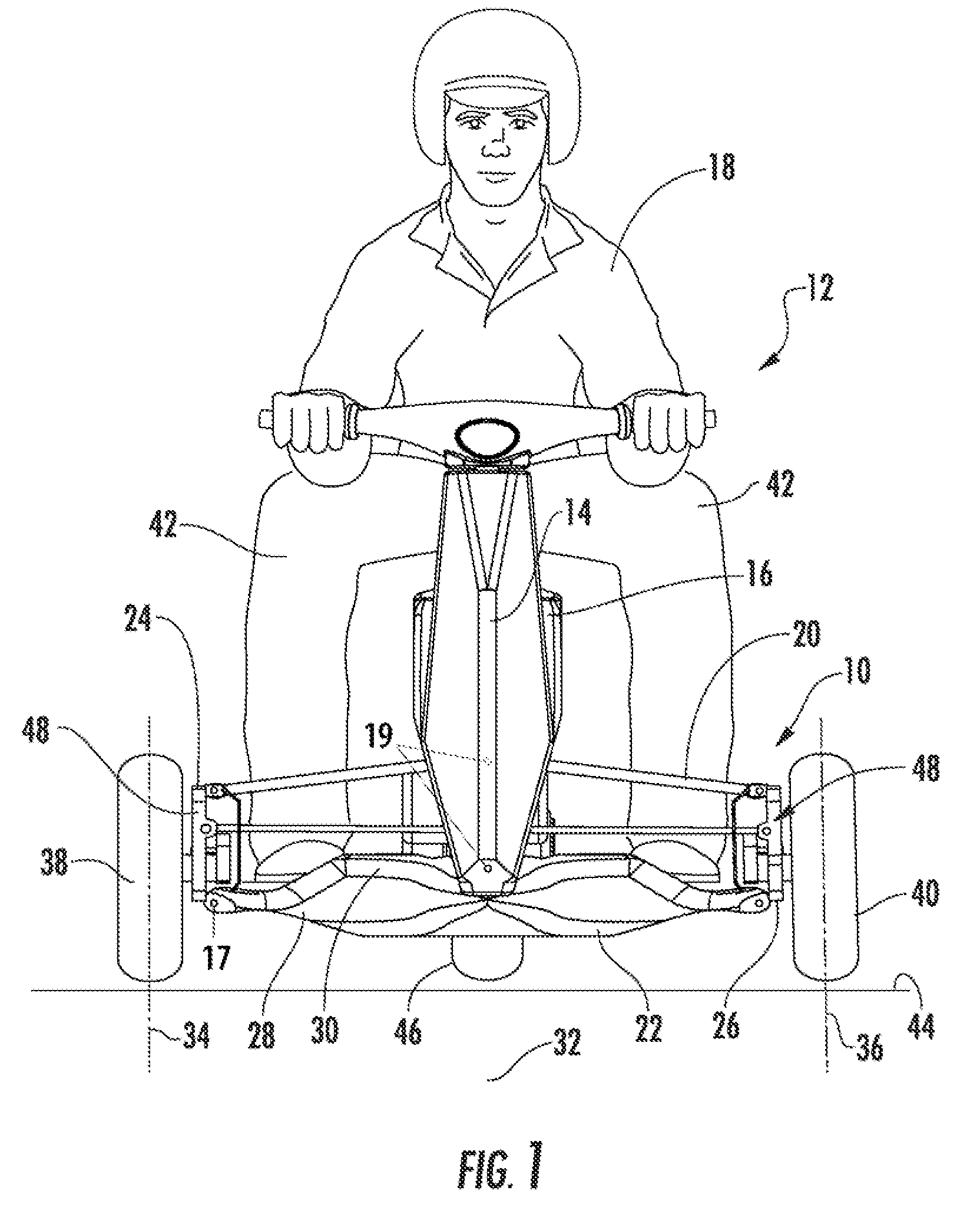
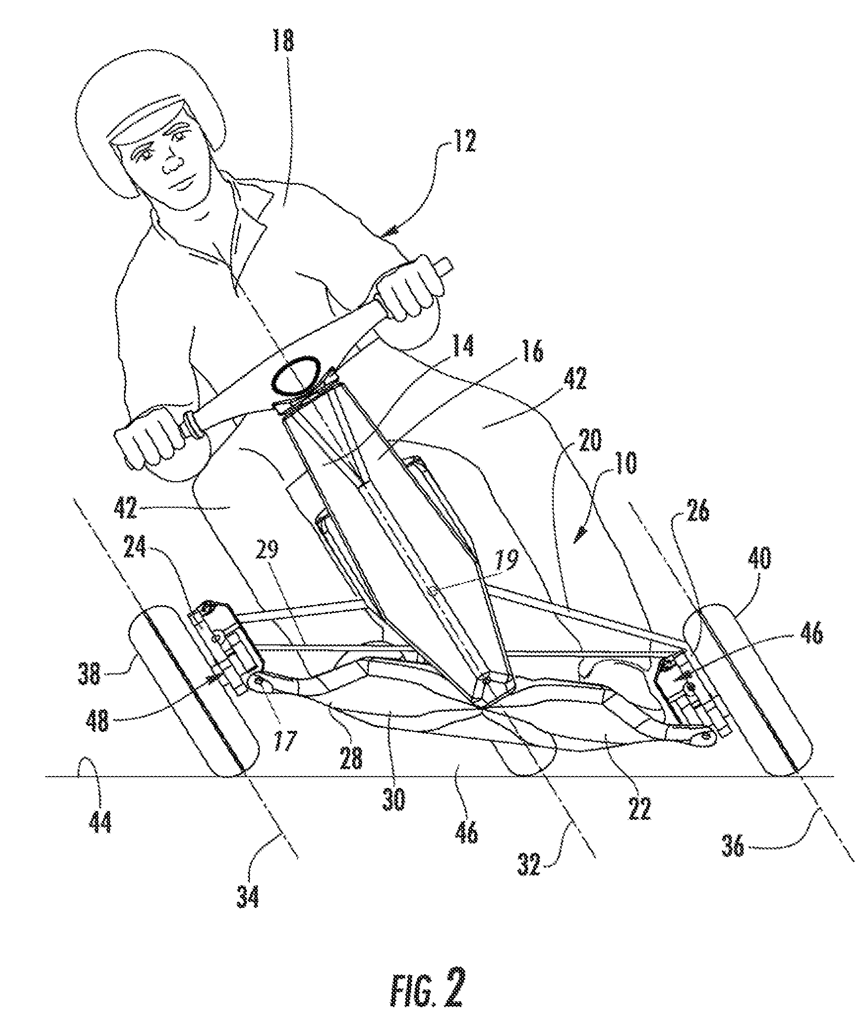
[0025]Now referring to the drawings, the suspension assembly for a tilting vehicle is shown and generally illustrated in the figures. FIGS. 1-5 depict the suspension assembly 10 as being installed at the front of a three-wheeled tilting vehicle. FIG. 6 depicts the suspension assembly 10 positioned at the rear of a vehicle. FIGS. 7-10 depict a vehicle that employs the suspension assembly 10 of the present invention both in the front and rear in a four-wheeled arrangement and an elongated configuration designed to carry multiple passengers. Finally, FIGS. 11 and 12 depict wheel alternatives such as skis and pontoons to allow the vehicle to travel on snow or water.

[0026]As can be seen in FIGS. 1-4, the suspension system 10 of the present invention is depicted on a tilting vehicle 12 that is in an upright and a tilted position and is depicted in the context of a wheeled vehicle. In general terms, the suspension assembly 10 of the present invention includes a central frame 14 having a fr...


PUM


Abstract

A suspension system for a vehicle is provided that allows for the vehicle body to be tilted wherein the tilt is controlled by the operator's legs in a manner that greatly enhances the stability of the vehicle while producing a fun vehicle to operate. Further, the bottom member of the suspension system is structured in a manner that provides storage capacity for installation of heavy items such as battery banks in order to preserve a lowered center of gravity for the vehicle. The tilting suspension may be used in the context of three-wheeled vehicle having a single rear drive tire and two forward wheels, but apply equally to a four wheeled vehicle as well as to water craft operating on pontoons or snow vehicles operating on skis.

Description

CROSS-REFERENCE TO RELATED APPLICATIONS[0001]This application is related to and claims priority from earlier filed U.S. Provisional Patent Application No. 60 / 912,230, filed Apr. 17, 2007.BACKGROUND OF THE INVENTION[0002]The present invention relates to generally to a suspension system for tilting vehicles. More specifically, the present invention relates to an active suspension for a tilting vehicle that expands upon the four-bar principal by extending the lower suspension linkage to create a large storage platform that allows heavy objects, such as battery banks, to be installed into the vehicle while preserving a lowered center of gravity.[0003]Currently, most of the motor vehicles that are on the highways are four-wheeled vehicles that tend to be larger, heavier and, as a result less, fuel-efficient than three-wheeled motor vehicles. Despite the fact that four-wheeled vehicles can be seen to enjoy more widespread use and acceptance, there are several advantages that are provided ...

Claims


Application Information

Patent Timeline
Patent Type & Authority Patents(United States)
IPC IPC(8): B60G21/00
CPCB60G3/01B60G3/20B62K5/027B62K5/05B62K5/10B60G2200/144B60G2202/12B60G2204/82B60G2206/50B60G2300/122B60G2300/124B60G2300/45
Inventor WILCOX, JOSEPH
Owner SWAY MOTORSPORTS INC
Why Eureka
Try Eureka