Light for the passenger compartment of a motor vehicle

a passenger compartment and passenger lamp technology, applied in the field of interior lamps, can solve the problems of occupying occupying less suitable positions for interior lamps, and occupying less space for interior lamps, so as to save space for interior lamps

Active Publication Date: 2010-02-23
CHEMTRON RES
View PDF17 Cites 4 Cited by
  • Summary
  • Abstract
  • Description
  • Claims
  • Application Information

AI Technical Summary

Benefits of technology

[0002]An interior lamp of this type for a motor vehicle is disclosed in European Patent Document EP 1 344 684 A1. This interior lamp, which is for motor vehicles, is equipped with a lens made of glass or plastic which covers the lamp or lamps. On its surface, this lens has optical elements for scattering or deflection of the emitted light. Preferably, the interior lamp is to be used as a reading light. At least a portion of the optical elements provided on the lens have a first central, non-diffusely scattering area and a second, diffusely scattering area completely or partially surrounding this first area. This special structure in the edge area of the optical elements provided on the lens reduces the glare effect of the interior lamp or of the reading light generated by the latter. The edge areas of the optical elements, which primarily are not intended for the light distribution, by means of their diffusely scattering surface structure, reduce the glare for the vehicle occupants or the observers.
[0003]This type of interior lamp has the disadvantage that it is generally arranged separately from a glass roof. The glass surface or the glass roof and the interior lamp therefore require space. Particularly with a glass roof, the space where the interior lamp is normally situated is occupied by the glass roof. This has the result that the interior lamp has to be arranged at a less suitable location. This results in a less optimal illumination of the vehicle interior.
[0004]It is therefore an object of the invention to create a construction of the interior lamp which can easily be integrated into a glass surface and therefore requires no additional space.
[0006]The interior lamp is advantageously installed directly into the glass roof, so that, when the light source is switched off, only a small frame separating the glass of the lens of the interior lamp from the glass pane of the glass roof will be visible. The glass of the interior lamp is as transparent with respect to light as the normal glass of the glass roof. The function of the glass roof is not limited by the arrangement of the interior lamp in the glass roof. The switching-on of the interior lamp, for example, when it is dark, causes the light output from the glass. As a result, the entire output surface is used as a lamp. This results in a saving of space for the interior lamp, because the interior lamp is integrated in the space of the already existing glass roof.

Problems solved by technology

This type of interior lamp has the disadvantage that it is generally arranged separately from a glass roof.
The glass surface or the glass roof and the interior lamp therefore require space.
This has the result that the interior lamp has to be arranged at a less suitable location.
This results in a less optimal illumination of the vehicle interior.

Method used


Image

  • Light for the passenger compartment of a motor vehicle
  • Light for the passenger compartment of a motor vehicle
  • Light for the passenger compartment of a motor vehicle

Examples


Embodiment Construction

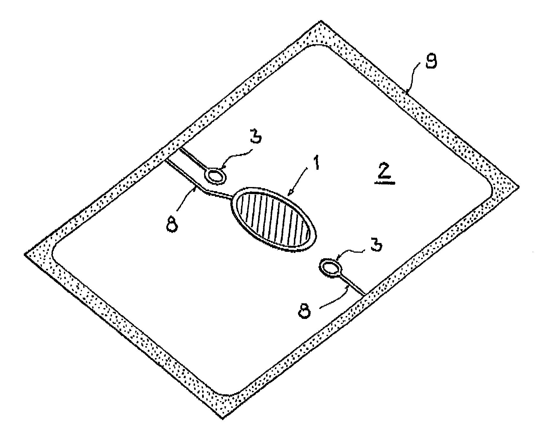
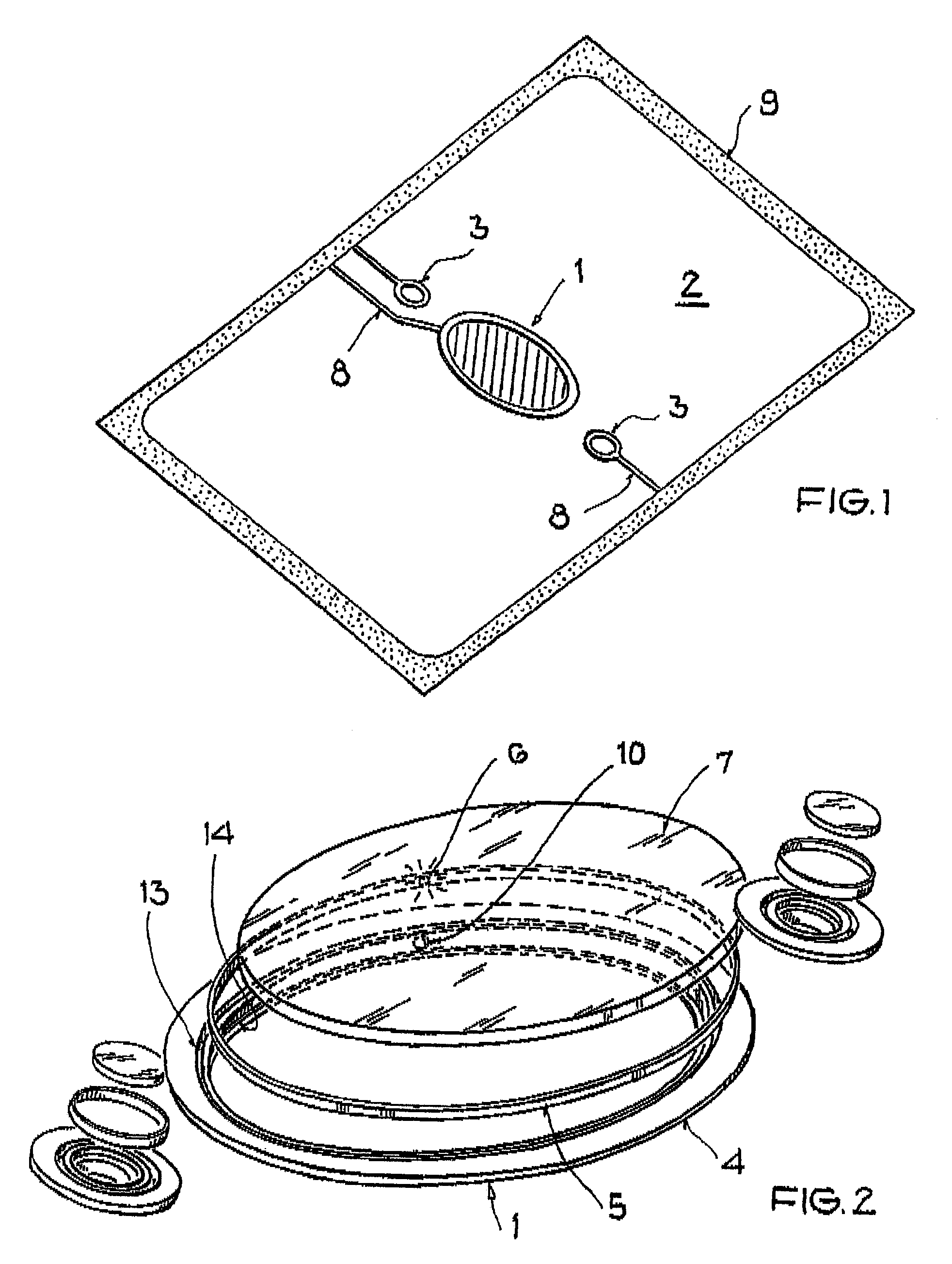
[0012]FIG. 1 is a schematic representation of an interior lamp in the glass roof 2 of a motor vehicle. The interior lamp, with one central light 1 and two “down” lights 3, is arranged in recesses in the glass of the glass roof 2. The interior lamp 1, 3 has a housing 4, which has a ring-shaped printed-circuit board 5 with light-emitting diodes 6 and the pertaining electronic system. The lamp also has a ring-shaped receiving slot for the printed-circuit board 5 in the housing 4 and an output element 7, which is arranged inside the housing 4 and preferably corresponds to a glass pane. The supply and control of the printed-circuit board 5 takes place by way of leads 8, which are integrated in the glass, preferably a laminated glass, of the glass roof 2, similar to a heatable rear window pane. The leads 8 extend from the glass frame 9 to the housing 4 into which the printed-circuit board 5 and the output element 7 are inserted.

[0013]As illustrated in FIG. 2, the light-emitting diodes 6 a...


PUM


Abstract

An interior lamp is provided for illuminating an interior of a vehicle having a glass surface, particularly a glass roof. At least one such interior lamp is integrated in the laminated glass of the glass surface.

Description

BACKGROUND AND SUMMARY OF THE INVENTION[0001]This invention relates to an interior lamp for transport devices, such as an aircraft or a motor vehicle.[0002]An interior lamp of this type for a motor vehicle is disclosed in European Patent Document EP 1 344 684 A1. This interior lamp, which is for motor vehicles, is equipped with a lens made of glass or plastic which covers the lamp or lamps. On its surface, this lens has optical elements for scattering or deflection of the emitted light. Preferably, the interior lamp is to be used as a reading light. At least a portion of the optical elements provided on the lens have a first central, non-diffusely scattering area and a second, diffusely scattering area completely or partially surrounding this first area. This special structure in the edge area of the optical elements provided on the lens reduces the glare effect of the interior lamp or of the reading light generated by the latter. The edge areas of the optical elements, which primar...

Claims


Application Information

Patent Timeline
Patent Type & Authority Patents(United States)
IPC IPC(8): B60Q3/02F21W106/00
CPCB32B17/10036B60Q3/0213B60Q3/208
Inventor SPAZIER, NORBERT
Owner CHEMTRON RES
Why Eureka
Try Eureka