Carbide drill bit for composite materials

a technology of carbide drill bits and composite materials, which is applied in the direction of twist drills, manufacturing tools, wood boring tools, etc., can solve the problems of cfrp components that are difficult to drill, and have a tendency to delaminate and fray, and interfere with the proper fit of the fastener

Active Publication Date: 2010-02-23
PRECORP INC
View PDF54 Cites 50 Cited by
  • Summary
  • Abstract
  • Description
  • Claims
  • Application Information

AI Technical Summary

Problems solved by technology

Drilling of CFRP components is often difficult as a result of the highly abrasive nature of the material and has a tendency to delaminate and fray when processed using conventional drill bits.
One of the more serious problems experienced in drilling CFRP occurs when the exit of the drill bit from the produced hole leaves uncut fibers exposed in the hole.
Such fibers then may interfere with the proper fit of the fastener used to join the materials.
While many of the components lend themselves to being manufactured with NC or CNC drilling machines, there remains a portion of the holes in the structure that cannot be manufactured with such equipment and may require a hand held air drill motor to be used.
Unfortunately, the drill bit may often surge at the point it exits the material on the backside, due to a lack of a controlled feed, resulting in uncut fibers.
Even with considerable skill and experience, an unacceptable hole is often produced by this method.
Such straight flute drill bits are often difficult to control at exit and in addition may produce a star shape hole as opposed to a round hole in the material.
The uncut exit fibers combined with the star shaped hole may result in a less than optimum fit of the fastener in joining the materials.
Fatigue results for parts fastened with inferior hole quality.
Such inferior hole quality often shows a marked reduction in fatigue life adversely affecting the suitability of the components in advanced aircraft structures.

Method used


Image

  • Carbide drill bit for composite materials
  • Carbide drill bit for composite materials
  • Carbide drill bit for composite materials

Examples


Embodiment Construction

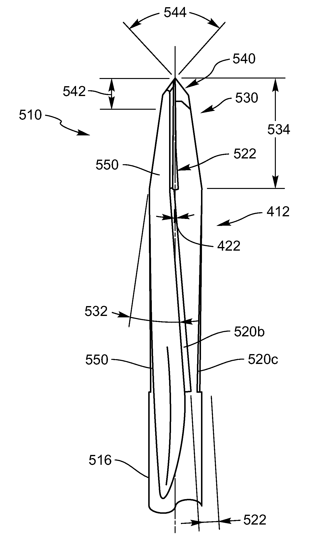
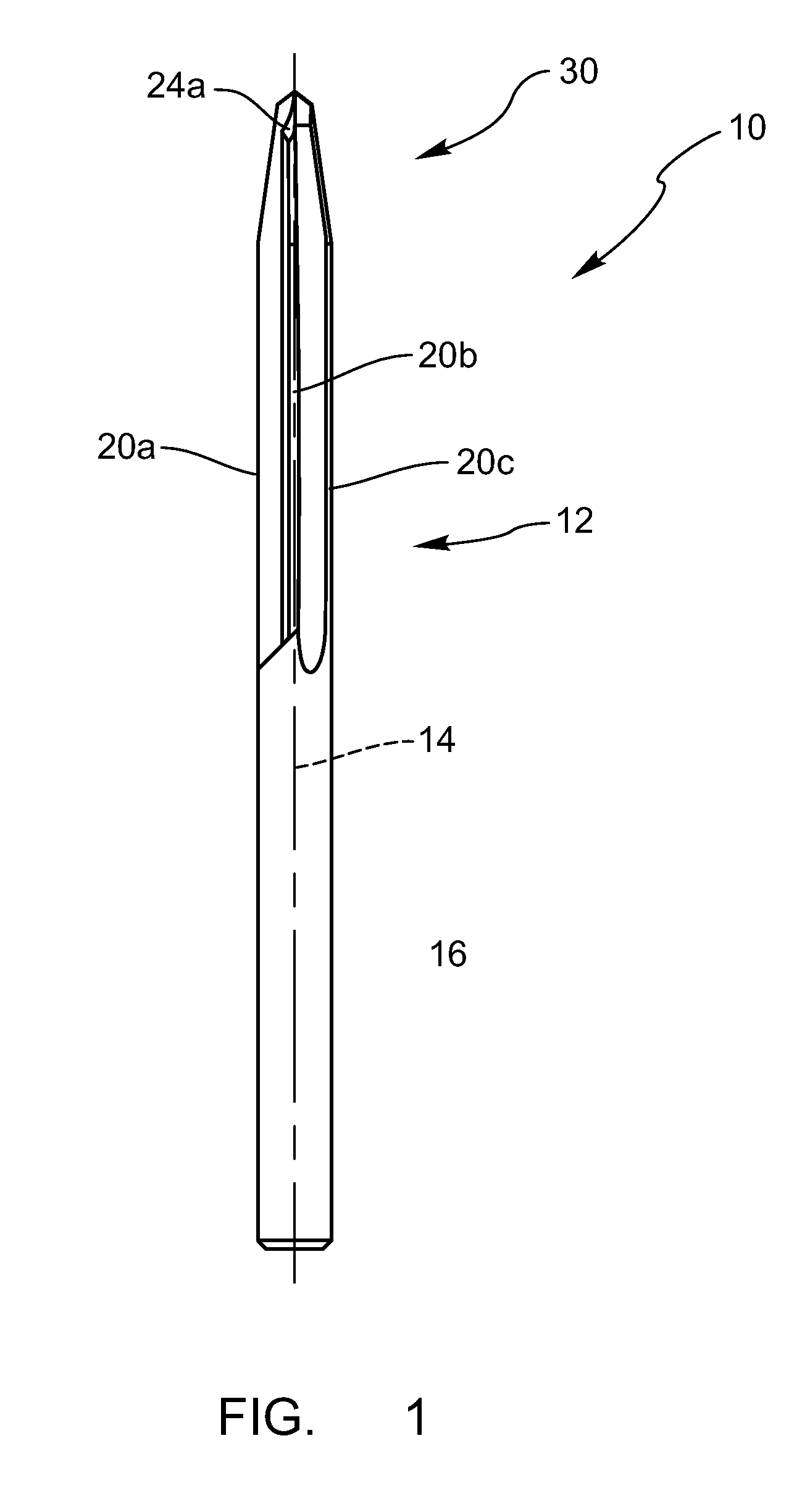
[0029]The embodiments of the present invention will be best understood by reference to the drawings. It will be readily understood that the components of the present invention, as generally described and illustrated in the figures herein, could be arranged and designed in a wide variety of different configurations. Thus, the following more detailed description of the embodiments of the drill bits of the present invention, as represented in FIGS. 3 through 7, is not intended to limit the scope of the invention, as claimed, but is merely representative of present embodiments of the invention. In order to illustrate a practical use of the drill bits of the present invention, the following description will illustrate the use of the drill bits in connection with advanced composite materials, such as CFRP. Of course, the drill bits of the present invention may be configured to drill materials such as wood, masonry, metals, and any other present or future materials.

[0030]Referring first to...


PUM

PropertyMeasurementUnit
radial rake angleaaaaaaaaaa
helix angleaaaaaaaaaa
tip angleaaaaaaaaaa

Abstract

A drill bit for producing holes in composite materials is disclosed. The drill bit includes an elongate drill bit body having a drill bit diameter. The drill bit also includes at least two helical flutes. The helical flutes have a reverse helix angle and a primary cutting edge. The primary cutting edge may have a positive rake angle. The drill bit further includes a point having a point length. The drill bit may also include a cutting tip with a tip angle and a tip length. The tip length is at least twice the drill bit diameter.

Description

TECHNICAL FIELD[0001]The present invention relates generally to drills and drill bits. More specifically, the present invention relates to carbide drill bits for composite materials.BACKGROUND[0002]Multi-layer laminates such as carbon fiber-reinforced composites (CFRP) and fiberglass composites (FRP) are widely used in a large number of applications. These laminate materials most often consist of woven layers of strong fibers that are often coated with resins and processed or cured to form a solid structure. Depending on the choice of the fiber and the resin systems used, these materials can be formulated and molded to produce components with excellent mechanical properties and unique geometries that would be difficult or impossible to obtain using other materials.[0003]The properties of high strength CFRP materials may be widely varied by manipulating the characteristics of the matrix formulation, as well as the fiber type, content, orientation, buildup, and the methods used to sha...

Claims


Application Information

Patent Timeline
Patent Type & Authority Patents(United States)
IPC IPC(8): B23B51/02
CPCB23B35/005B23B51/02B23B2215/04B23B2226/27B23B2226/275Y10T408/9097B23B2251/043B23B2251/082B23B2251/14B23B2251/18Y10T408/909B23B2251/04
Inventor GARRICK, RICHARD M.BUNTING, JOHN A.
Owner PRECORP INC
Why Eureka
Try Eureka