
Electronic device and circuit for providing tactile feedback

a technology of tactile feedback and electronic devices, applied in the direction of generators/motors, pulse techniques, instruments, etc., can solve the problems of difficult optimization of piezoelectric actuator drive circuits, the domino switch does not function well with morphing graphic user interfaces, and the inability to selectively feedback individual input locations (keys, buttons, arrows, etc., to achieve low cost

Active Publication Date: 2010-02-23
GOOGLE TECHNOLOGY HOLDINGS LLC
View PDF16 Cites 66 Cited by
  • Summary
  • Abstract
  • Description
  • Claims
  • Application Information

AI Technical Summary

Benefits of technology

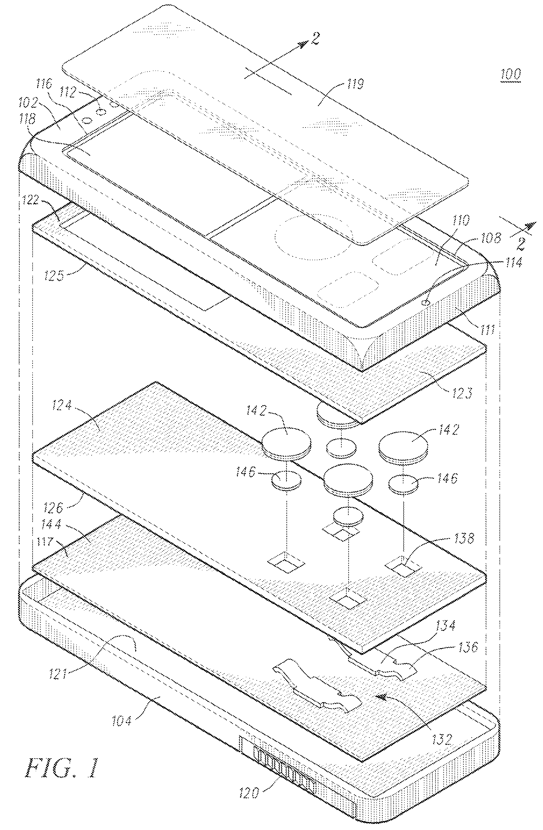
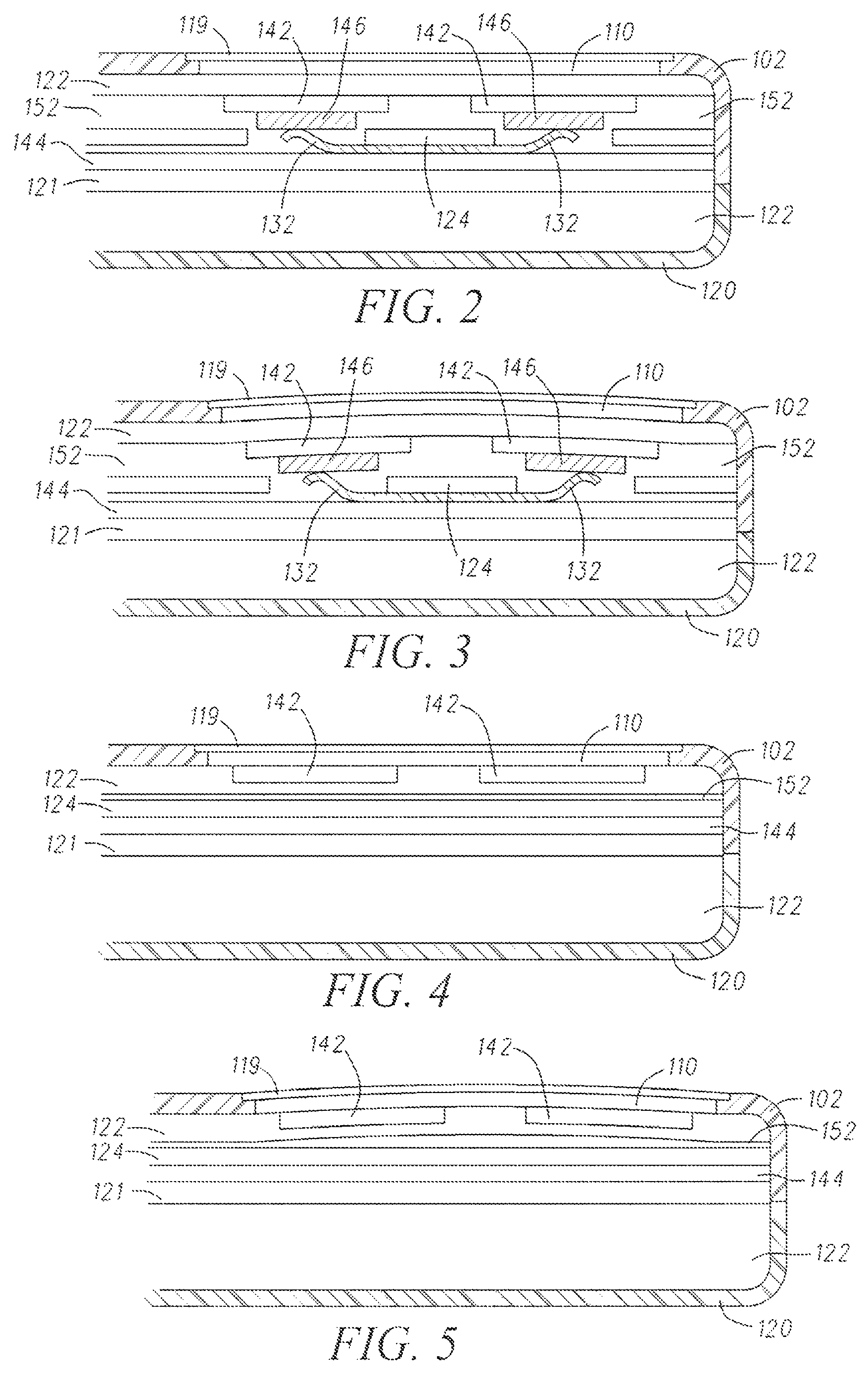
The patent describes a way to create a thin and affordable device that can provide a click-like feel to electronic devices. The device uses a piezoelectric device that is activated when the user presses a button on the device. The device then flexes to create the click-like feel. This technology can be used to create a more tactile and user-friendly experience for electronic devices.

Problems solved by technology

However, dome switches do not function well with morphing graphic user interfaces; therefore, haptics or active feedback becomes a critical enabler.
This mechanism is suitable for providing a “call alert” which vibrates the entire device, but does not allow for selective feedback to individual input locations (keys, buttons, arrows, etc).
It is challenging to optimize piezoelectric actuator drive circuits for handheld devices.
As such, these circuits are non-optimal for generating a positive voltage waveform as required to simulate a key click tactile feel.
Not only are they overly complex and costly to implement, but if driven at a high enough voltage, they can even de-polarize the piezoceramic element and thus render piezoelectric unimorph actuators ineffective.
In addition, solutions have been proposed in which arbitrary predefined waveforms such as saw-tooth, sine, half sine, and pulse, are played to create specific haptics effects based on a user input; however, such solutions teach no method of generating such signals and do not teach a suitable method of generating such signals at high enough voltages to drive a piezoelectric unimorph actuator.

Method used


Image

  • Electronic device and circuit for providing tactile feedback
  • Electronic device and circuit for providing tactile feedback
  • Electronic device and circuit for providing tactile feedback

Examples


Embodiment Construction

[0024]The following detailed description of the invention is merely exemplary in nature and is not intended to limit the invention or the application and uses of the invention. Furthermore, there is no intention to be bound by any theory presented in the preceding background of the invention or the following detailed description of the invention.

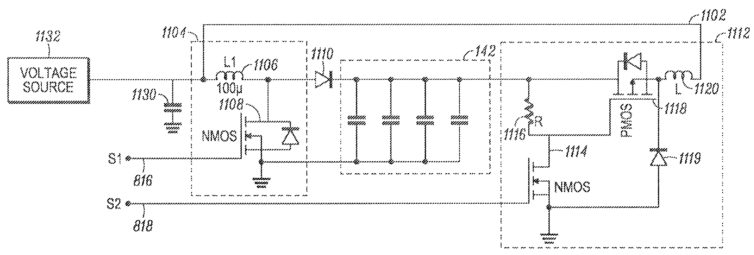
[0025]The electronic circuitry for controlling at least one piezoelectric actuator includes a piezoelectric actuator drive circuit that includes a pulsed, inductive boost charging circuit, operatively responsive to a first pulse-width-modulated control signal, and a pulsed constant-current-sink discharge circuit that is operatively responsive to a second pulse-width-modulated control signal. The pulse-width-modulated control signals may be such that the duty cycle remains constant, or the duty cycle may vary as a function of time. The pulsed inductive boost circuit controllably adds pre-determined “packets” of charge to the piezoelectric act...


PUM


Abstract

A circuit (800) for controlling at least one piezoelectric actuator (142) includes a piezoelectric drive circuit (802) that generates unidirectional voltage drive signal, also referred to as Vout, at node (804). The piezoelectric actuator drive circuit (802) includes a boost switcher circuit or charging circuit (806), a buck switcher circuit or pulsed current sink discharge circuit (808) and a control signal generating circuit (810) that receives an input control signal (812) from, for example, a keyboard processor or other suitable processor (604) indicating that the device has requested generation of haptic feedback utilizing the piezoelectric actuator (142). The control signal generating circuit (810) provides at least two pulse-with-modulated control signals, one to control the charging circuit and one to control the discharging circuit to produce the unidirectional voltage drive signal, that in one example is a raised cosine drive signal (904).

Description

RELATED CO-PENDING APPLICATION[0001]This application is related to co-pending application Ser. No. 11 / 590,494, having as inventors Dai et al., entitled “Electronic Device Providing Tactile Feedback” filed on Oct. 30, 2006, and owned by instant assignee.FIELD OF THE INVENTION[0002]The present invention generally relates to electronic devices and more particularly to a portable communication device having tactile feedback.BACKGROUND OF THE INVENTION[0003]Morphing user interfaces will be an important design consideration for the next generation of portable electronic devices. A “morphing user interface” is an interface whose appearance changes as the device's use changes (e.g., from a phone to a camera, camera to music player, music player to phone, etc.). This input interface is simpler and more intuitive to use since only the context-relevant functions are shown at any given time, with the interface elements that are not related to the current context being inactive and hidden. The c...

Claims


Application Information

Patent Timeline
Patent Type & Authority Patents(United States)
IPC IPC(8): H01L41/08H10N30/00H10N30/20H10N30/80
CPCG06F1/3203G06F3/016H01L41/042H10N30/802H03K2217/96062H10N30/20
Inventor SADLER, DANIEL J.CRANFILL, DAVID B.OLLEY, MICHAEL F.TASHAKKOR, ERIC V.WAGNER, DANIEL H.
Owner GOOGLE TECHNOLOGY HOLDINGS LLC
Learn More