Method and apparatus for synchronization of a mobile radio receiver to a base station

a mobile radio receiver and synchronization technology, applied in the direction of synchronizing arrangement, electrical equipment, digital transmission, etc., can solve the problems of increasing processing effort, achieve the effect of improving synchronization performance, increasing processing bandwidth of the apparatus, and reducing the cost of time resolution capability

Inactive Publication Date: 2010-02-23
INTEL CORP
View PDF11 Cites 10 Cited by
  • Summary
  • Abstract
  • Description
  • Claims
  • Application Information

AI Technical Summary

Benefits of technology

[0010]The invention is directed to a method as well as an apparatus for synchronization of a mobile radio receiver to a base station which ensures significantly better synchronization performance, particularly for an initial synchronization procedure (initial cell search), without increasing the processing time period in comparison to the prior art.
[0012]In other words, the sampling phases that are generated in the receiver are processed at different frequencies. Synchronization attempts can be carried out at the same time at these different frequencies. In the case of a signal which has been oversampled N times up to N frequencies may be searched through at the same time. This therefore results (with the exception of the complexity for frequency shifting) in no increase in the processing effort, since the increase in the processing bandwidth is at the expense of the time resolution capability. Furthermore, in comparison to the prior art, this does not result in any lengthening of the processing time period (that is to say, no lengthening of the acquisition time or of the time for negative detection) since the same frequency search grid is used as in the prior art, so that the number of synchronization attempts is not increased.
[0016]The apparatus according to the invention has a means for correlation of the oversampled signal with a local code, with sample values that are associated with a first sampling phase being processed with a frequency offset with respect to sample values that are associated with a second sampling phase. As already mentioned, the increase in the processing bandwidth of the apparatus results in a significant improvement in the synchronization performance, at the expense of the time resolution capability.

Problems solved by technology

This therefore results (with the exception of the complexity for frequency shifting) in no increase in the processing effort, since the increase in the processing bandwidth is at the expense of the time resolution capability.

Method used


Image

  • Method and apparatus for synchronization of a mobile radio receiver to a base station
  • Method and apparatus for synchronization of a mobile radio receiver to a base station
  • Method and apparatus for synchronization of a mobile radio receiver to a base station

Examples


Embodiment Construction

[0030]First of all, in order to assist understanding of the following text, an example of a mobile radio standard (UMTS) will be used to explain the steps that have to be carried out by a mobile station during an initial cell synchronization process. In this case, the channel structure is based, by way of example, on the UMTS Standard.

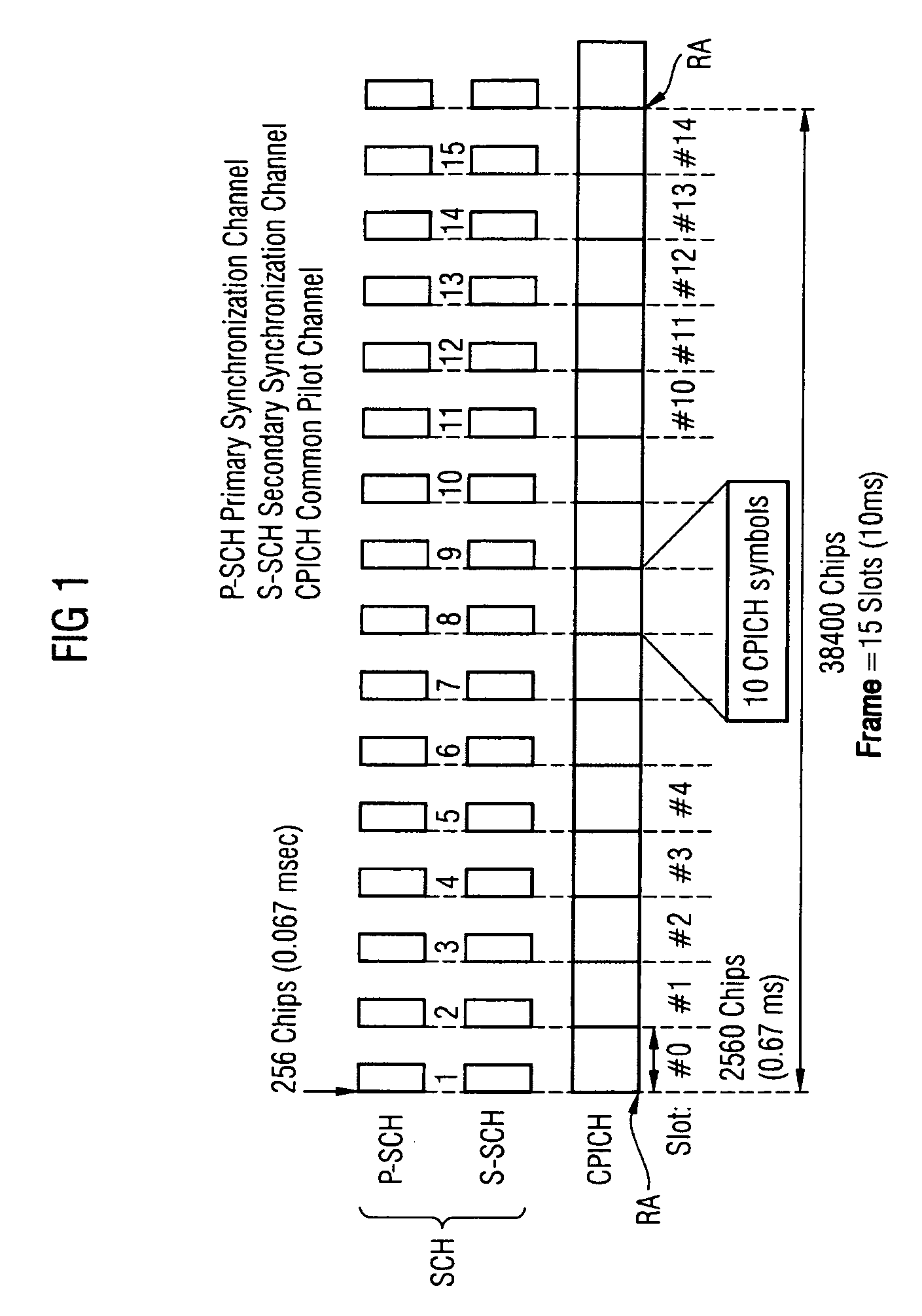
[0031]As is shown in FIG. 1 a UMTS frame comprises 15 slots (#0, #1, . . . , #14). Each slot may contain 2560 chips. The chip time duration Tchip in the UMTS Standard is 0.26 μs. In consequence, the slot time duration is 0.67 ms, and the frame duration is 10 ms.

[0032]Two UMTS channels are involved in the synchronization of the mobile station to a base station (cell search), specifically the synchronization channel SCH and the common pilot channel CPICH. The synchronization channel SCH comprises a first synchronization channel P-SCH (Primary Synchronization Channel) and a second synchronization channel S-SCH (Secondary Synchronization Channel). At the s...


PUM


Abstract

In a method for synchronization of a mobile radio receiver to a base station, the received signal is sampled using oversampling, by which means sample values are obtained from different sampling phases. The oversampled signal is correlated with a local code, with sample values that are associated with a first sampling phase being processed with a frequency offset with respect to sample values that are associated with a second sampling phase.

Description

REFERENCE TO RELATED APPLICATIONS[0001]This application claims the benefit of the priority date of German application DE 103 51 649.2, filed on Nov. 5, 2003, the contents of which are herein incorporated by reference in their entirety.FIELD OF THE INVENTION[0002]The invention relates to a method and an apparatus for synchronization of a mobile radio receiver to a base station when there is a frequency offset between the transmitter (base station) and the mobile radio receiver.BACKGROUND OF THE INVENTION[0003]Before setting up a data connection to one or more base stations, the transmission clock and reception clock in each mobile radio receiver must be synchronized. This is generally achieved by means of a three-step method: slot synchronization (time slot synchronization) is carried out in a first synchronization step. Once the slot timings are known, the frame boundaries of the signal are determined in a second synchronization step (a frame synchronization). The scrambling code th...

Claims


Application Information

Patent Timeline
Patent Type & Authority Patents(United States)
IPC IPC(8): H04L7/00H03K7/04H04B1/707H04Q7/38
CPCH04B1/70757H04B1/70735
Inventor PAUL, STEFFENRUPRICH, THOMASJALLOUL, LOUAY
Owner INTEL CORP
Why Eureka
Try Eureka