
Structure of a measuring tape device

a technology of measuring tape and structure, which is applied in the direction of measuring devices, instruments, and mechanical means, can solve the problems of inability to meet the requirements of measurement accuracy, so as to achieve the effect of improving the structure of the measuring tape device and ensuring the accuracy of measuremen

Active Publication Date: 2010-03-02
TECHTRONIC POWER TOOLS TECHNOLOGY LTD
View PDF10 Cites 37 Cited by
  • Summary
  • Abstract
  • Description
  • Claims
  • Application Information

AI Technical Summary

Benefits of technology

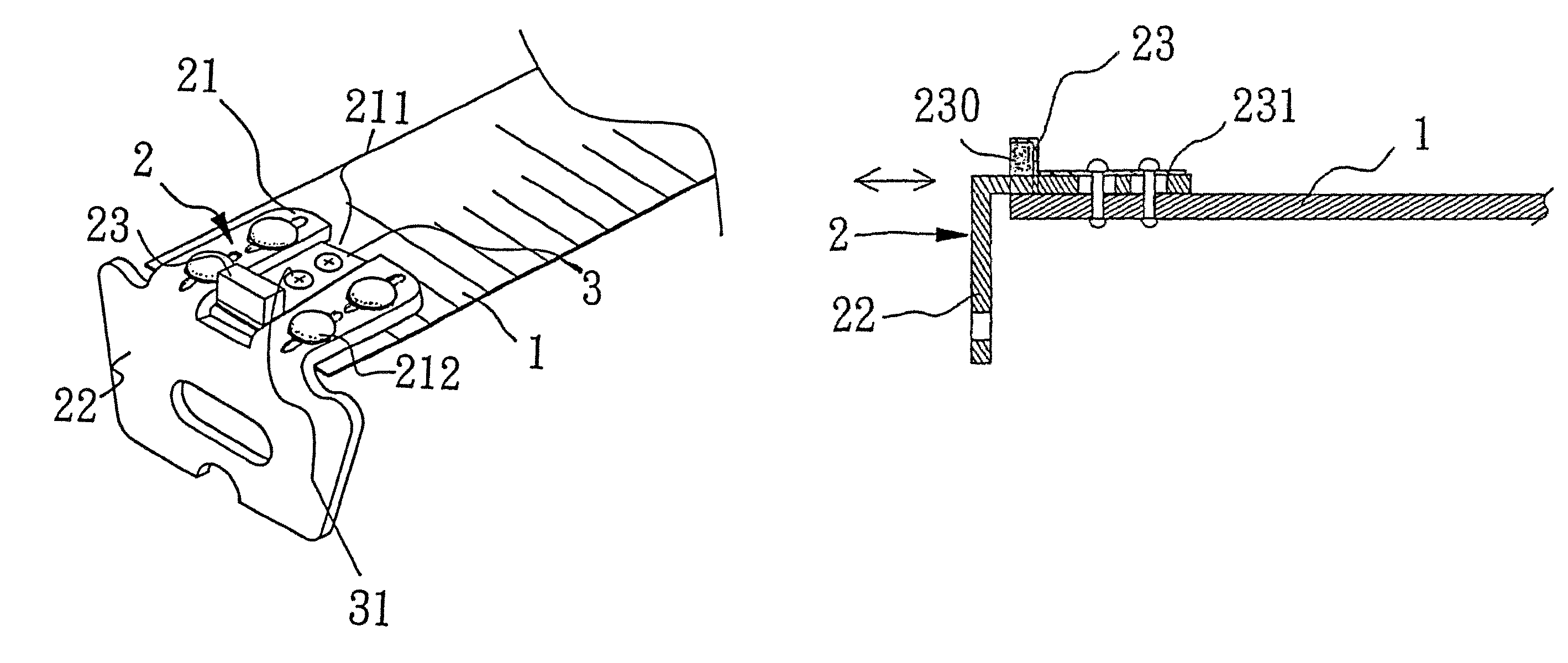
[0009]The improvement on the structure of a measuring tape device of present invention is that a magnetic mechanism is to be secured at the distal end of a measuring tape, the magnetic mechanism is placed in alignment at the “0” cm mark on the measuring tape, and therefore there will not be the issue of thickness variation of the hook member. As such, one of the objectives of present invention is that the setting of the magnetic mechanism is in such a way that it will not affect the precision of measurement when measuring the distance / length of an object of measurement and a designated point.
[0011]According to the above objectives, the improvement on the structure of a measuring tape device of present invention is that the magnetic mechanism is secured at the distal end of the measuring tape, the magnetic mechanism is not placed onto and to be formed as part of the body of the leg piece of the hook member, the magnetic mechanism is set in alignment at the “0” cm mark on the measuring tape; the mechanism enables the distal end of the tape to be magnetically attached to any specific article, for example, to pick up small metallic articles at places that cannot be reached by hands, or by using the distal end of the tape to push against or hook onto places where conventional hook member cannot be applied. At the same time, during the measuring process of an object of measurement and a designated point, the magnetic mechanism allows the measuring tape to be magnetically attached to the surface of the object and anchored at the exact starting point of measurement, therefore, the measuring precision will not be skewed because of the thickness of the hook member or because of the gap caused by the movable mechanics of the hook member.

Problems solved by technology

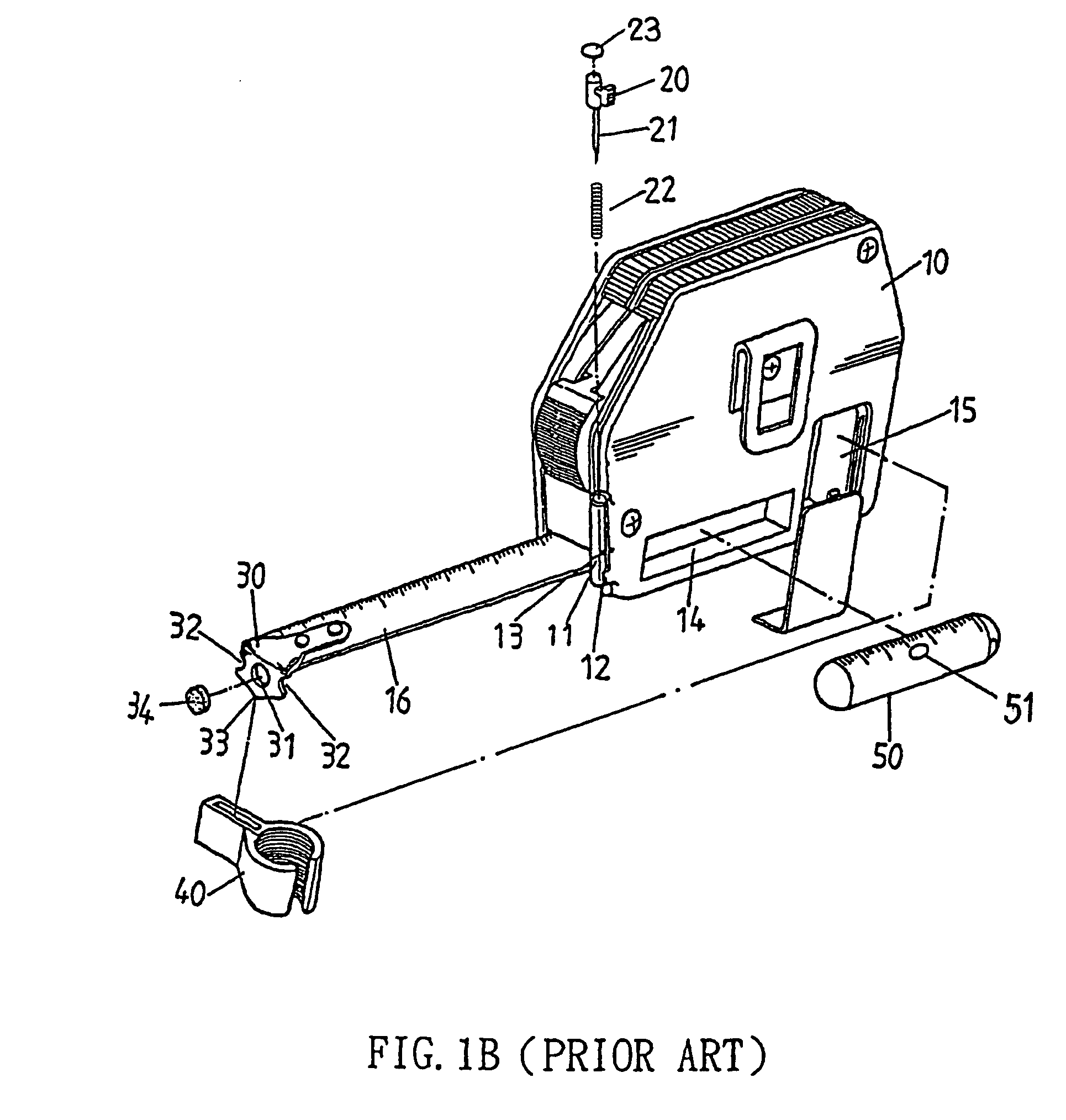
However, for a conventional measuring tape device, the hook member 13 can only be applied to either hook onto or push against an object of measurement; in the case that the measurement is to be applied on a flat / smooth surface, it often happens that there is no anchor point for the hook member, so that the measuring process can only be carried out with the surface of the measuring tape loosely glides along the top of and / or pushes against the surface of the object of measurement.
Since there is no fastened grip at the distal end of the measuring tape for a proper measurement, the process and the outcome of the measurement is therefore inevitably affected.
Yet during measuring process, when a hook member was to be pushed against or magnetically attached to the metallic surface of the object of measurement, these designs still resulted in measurement imprecision caused by thickness of the hook member and / or the gap d that was effected from the movable mechanics of the hook member.
Besides, the magnetic piece mentioned in most of the above inventions was mounted onto a mount opening of a hook member of the measuring tape, as such, in the case that the measuring tape device was to be dropped or if the hook member was to be impacted with another hard object, then there would be a great chance that the magnetic piece to be fell off the hook member, and thus caused operational nuisance.

Method used


Image

  • Structure of a measuring tape device
  • Structure of a measuring tape device
  • Structure of a measuring tape device

Examples


Embodiment Construction

[0023]The present invention relates to improvement on the structure of a measuring tape device, as shown in FIGS. 2 and 5, the structural improvement of measuring tape device of present invention is that a magnetic mechanism 23 is secured at the distal end of a measuring tape 1. The magnetic mechanism 23 is not placed onto the leg piece of the hook member 2 and thus is not formed as part of the body of the hook member 2 of the measuring tape 1, the front of the magnetic mechanism 23 is placed in alignment with the “0” cm mark on the measuring tape 1. The mechanism enables the distal end of the tape to be magnetically attached to any specific article, for example, to pick up small metallic articles at places that cannot be reached by hands, or by using the distal end of the tape to push against or hook onto places where conventional hook member cannot be applied. At the same time, during the measuring process of an object of measurement and a designated point, the magnetic mechanism ...


PUM


Abstract

An improvement on the structure of a measuring tape device is that a magnetic mechanism is secured at the distal end of a measuring tape. The magnetic mechanism is not placed onto the leg piece of the hook member and thus is not formed as part of the body of the hook member of the measuring tape. The front end of the magnetic mechanism is placed in alignment with the “0” cm mark on the measuring tape. During measuring process of an object of measurement and a designated point, the magnetic mechanism allows the measuring tape to be magnetically attached to the surface of the object and anchored at the exact starting point of measurement, and therefore, the measuring precision will not be skewed because of thickness of the hook member or because of the gap caused by the movable mechanics of the hook member.

Description

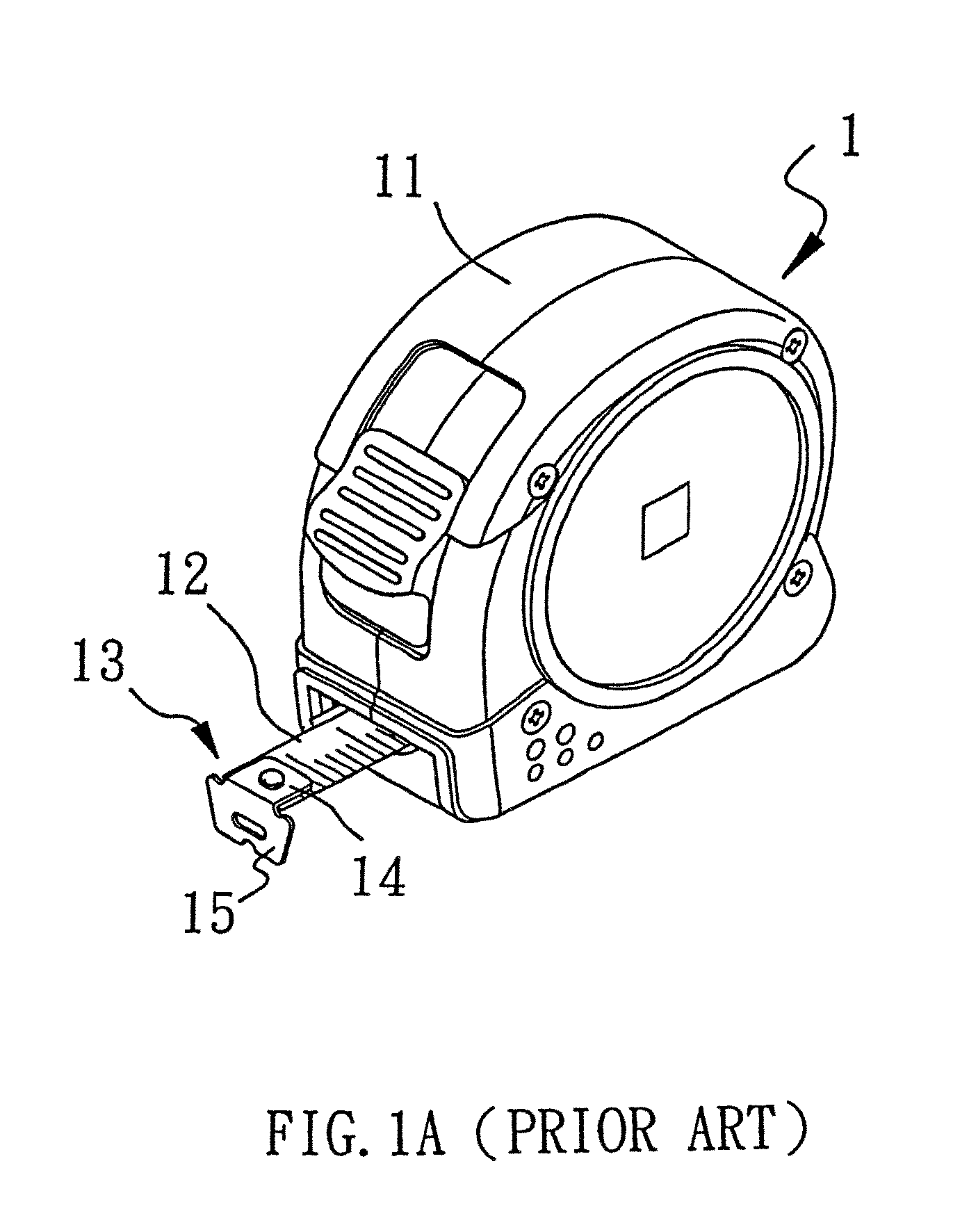
BACKGROUND OF THE INVENTION[0001]1. Field of the Invention[0002]The present invention relates to improvement on the structure of a measuring tape device, in particular, it refers to a measuring tape device with which the precision of measurement will not be skewed by thickness of the hook member located at the distal end of a measuring tape and / or the gap caused by the movable mechanics of the hook member.[0003]2. Description of Prior Art[0004]It is a known fact that measuring tape device is a rather mechanical and convenient device amongst various types of measuring tools. As shown in FIG. 1A, a conventional measuring tape device 1 contains a coilable tape 12 that is spring-loaded (not shown in the drawings) within a casing 11. The measuring tape device 12 has a hook member 13 secured to the distal end of a measuring tape. The hook member 13 is composed of two parts: (1) the backing plate 14 that is secured to the distal end of the tape by rivets and (2) the perpendicularly-extende...

Claims


Application Information

Patent Timeline
Patent Type & Authority Patents(United States)
IPC IPC(8): G01B3/08
CPCG01B3/1056
Inventor HUANG, JASON
Owner TECHTRONIC POWER TOOLS TECHNOLOGY LTD
Learn More