Door threshold water return systems

a technology of water return system and door threshold, which is applied in the direction of sill/threshold, construction, building components, etc., can solve the problems of creating safety hazards, damage, and deleterious effects on flooring and furnishings in homes and buildings

Inactive Publication Date: 2010-03-02
HENRY MICHAEL PAUL
View PDF30 Cites 61 Cited by
  • Summary
  • Abstract
  • Description
  • Claims
  • Application Information

AI Technical Summary

Benefits of technology

[0032]The present invention provides a door threshold water return system for preventing water entrained in higher pressure air at exterior of homes and buildings from entering interior of the homes or buildings during storm or wind driven rain, ice, hail, or snow events.
[0033]The inventive door threshold water return system can be used with a variety of types, sizes, and shapes of doors, door systems, door assemblies, door frames, jambs, homes, buildings, and the like. The inventive system can be installed in a quick, convenient, and efficient manner, and is easy and safe to use, attractive, sturdy, of simple construction, inexpensive to manufacture, durable, and long lasting. In addition, the inventive system can maintain its ability to return water that entered the system to the outside environment during storm events and prevent drafts over time, even in situations where repeated opening and closing of the door is necessary.
[0034]The inventive door threshold water return system, which can be used with existing door systems, directs water to enter the system from an interior side of the system and to exit from an exterior side of the system, towards a direction opposing increasing air pressure and air flow, thereby forcing water to flow out of the system in a direction of increasing air pressure. Since air flow is minimized through the inventive system, substantially all water entering the system from the interior side is returned to the exterior side, thereby preventing unwanted drafts.
[0035]The inventive door threshold water return system has a high degree of structural integrity, and is capable of use in a variety of situations. For example, in one embodiment, the system is provided with a sill angle to facilitate easy wheel chair ingress and egress.

Problems solved by technology

This occurrence can often create safety hazards, damage, and deleterious effects to flooring and furnishings within the homes and buildings.

Method used


Image

  • Door threshold water return systems
  • Door threshold water return systems
  • Door threshold water return systems

Examples


Embodiment Construction

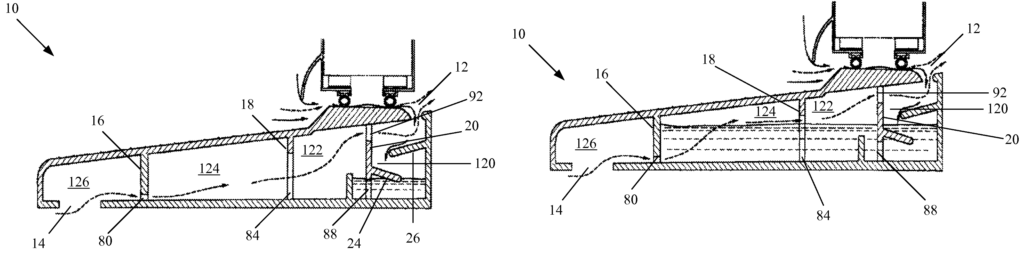
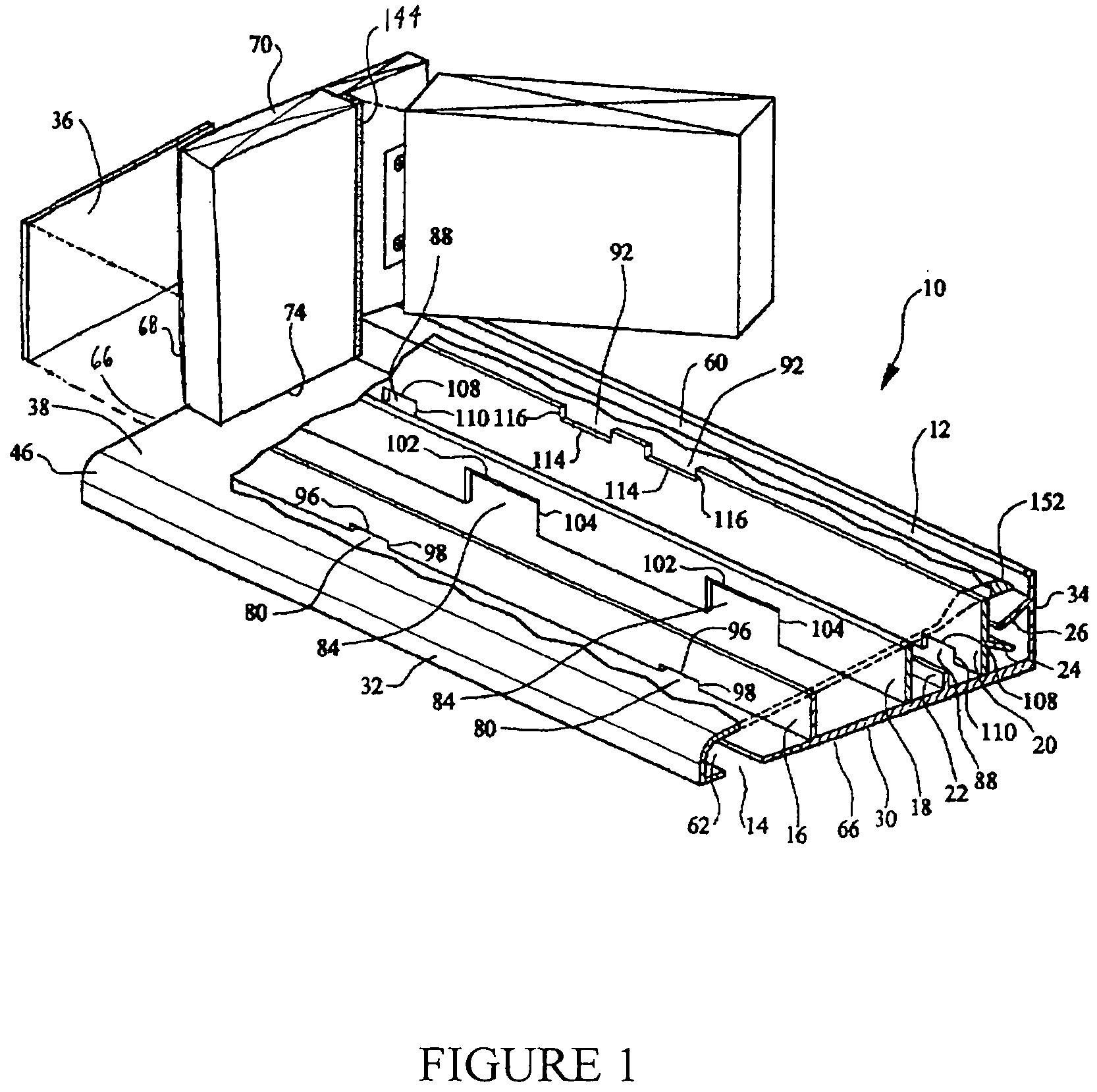
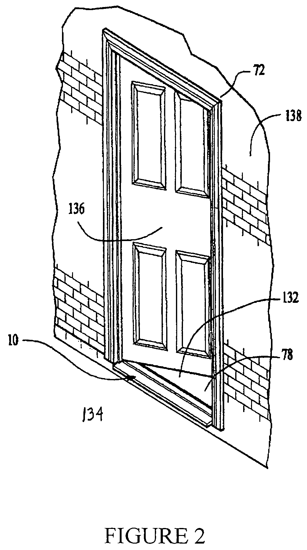
[0082]The present invention provides systems and methods for preventing water entrained in higher pressure air at exterior of homes and buildings from entering interior of the homes or buildings. The inventive door threshold water return system can generally be used with a variety of types, sizes, and shapes of doors, door systems, door assemblies, door frames, jambs, homes, buildings, and the like. The system can be installed in a quick, convenient, and efficient manner, and is easy and safe to use, attractive, sturdy, of simple construction, inexpensive to manufacture, durable, and long lasting. In addition, the system can maintain its ability to return water entering the system to outside environment during storm events and prevent drafts over time, even in situations where repeated opening and closing of the door is necessary.

[0083]The inventive door threshold water return system, which can be used with existing door systems, directs water to enter the system from an interior si...


PUM


Abstract

A door threshold water return system, comprising: a lower sill; an upper sill; a rear wall; and a front wall forming a chamber, wherein at least one baffle is provided projecting into the chamber from the rear wall, a first gap is provided in proximity to the rear wall and between the upper sill and the rear wall, and a second gap is provided in proximity to the lower sill and between the lower sill and the front wall, whereby water introduced into the system through the first gap exits the system through the second gap.

Description

CROSS REFERENCE TO RELATED APPLICATION[0001]This application claims priority under 35 U.S.C. §119(e) to U.S. Provisional Application No. 60 / 643,678, filed Jan. 12, 2005.FIELD OF THE INVENTION[0002]The present invention relates generally to water return systems, and more particularly to door threshold water return systems.BACKGROUND OF THE INVENTION[0003]Residential door systems typically have a threshold at the base of a door assembly, having a door, which generally has a door shoe having a door seal around the perimeter of the door. Storm or wind driven rain, ice, hail, or snow can create an air pressure differential across the threshold of the door, resulting in higher air pressure at the exterior of the door than that at the interior of the door. This air differential forces water to be entrained in the high pressure air as the air flows across the door seal, which can migrate around some imperfect door seals and enter into the interior and living quarters of homes and buildings....

Claims


Application Information

Patent Timeline
Patent Type & Authority Patents(United States)
IPC IPC(8): E06B1/70
CPCE06B1/70E06B7/14
Inventor HENRY, MICHAELHENRY, ANN
Owner HENRY MICHAEL PAUL
Why Eureka
Try Eureka