Spindle and method of orienting a spindle into a dial

a spindle and dial technology, applied in the field of combination locks, can solve the problems of inconvenient spindle installation, substantial financial hardship for locksmiths, and inability to standardize the length of the spindle used in combination locks, and achieve the effect of easy and quick modification

Inactive Publication Date: 2010-03-02
LEXAM SECURITY PROD
View PDF32 Cites 2 Cited by
  • Summary
  • Abstract
  • Description
  • Claims
  • Application Information

AI Technical Summary

Benefits of technology

[0011]Therefore, one object of the present invention is the provision of a novel dial and spindle construction for combination lock assemblies which may be readily conditioned by locksmiths in the field to adapt the unit for use in lock devices having a wide variety of hands of installation.
[0012]Another object of the present invention is the provision of a novel spindle for combination lock assemblies wherein the axial length of the spindle may be easily and quickly altered such that persons in the field can readily assemble the spindle with mechanical dials and lock devices mounted at various separation distances.

Problems solved by technology

However, having to stock a wide variety of spindles is not only inconvenient, but it also presents a substantial financial hardship to the locksmith.
In addition, the length of the spindles used in combination locks is not standardized and depends upon, for example, the separation distance between the dial on one side of the mounting surface and the lock on an opposing side of the mounting surface.
If this step is not taken, the spindle may, for example, tear or otherwise damage the cam in the lock device.

Method used


Image

  • Spindle and method of orienting a spindle into a dial
  • Spindle and method of orienting a spindle into a dial
  • Spindle and method of orienting a spindle into a dial

Examples


Embodiment Construction

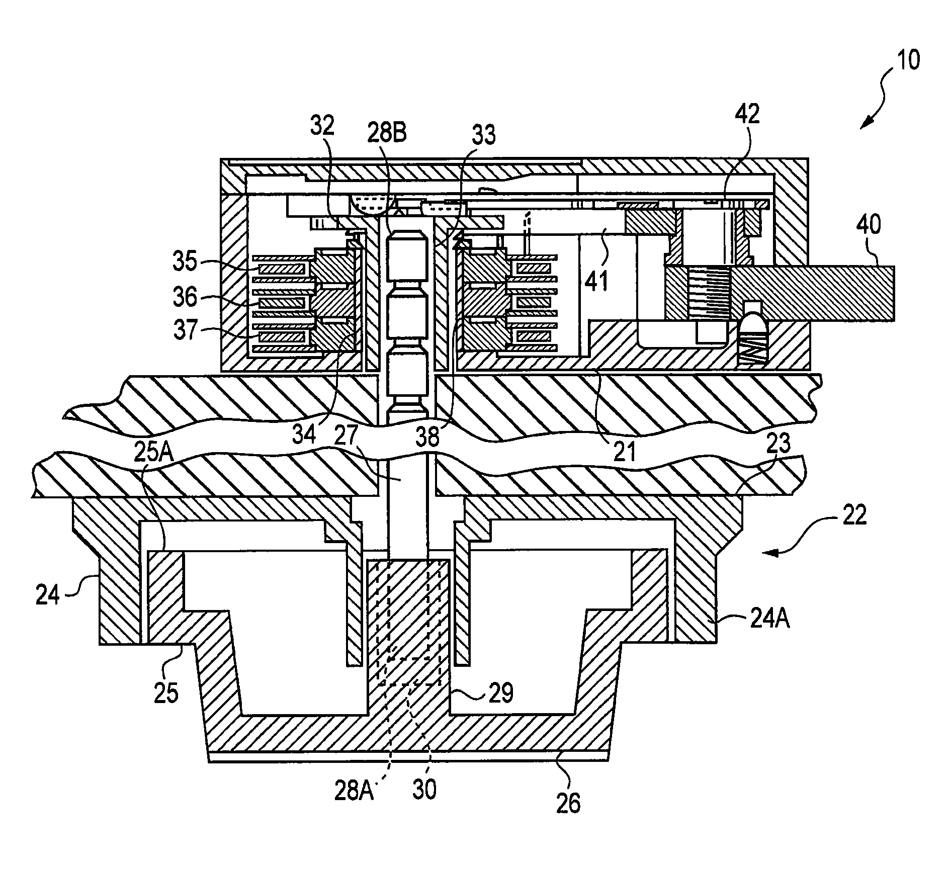
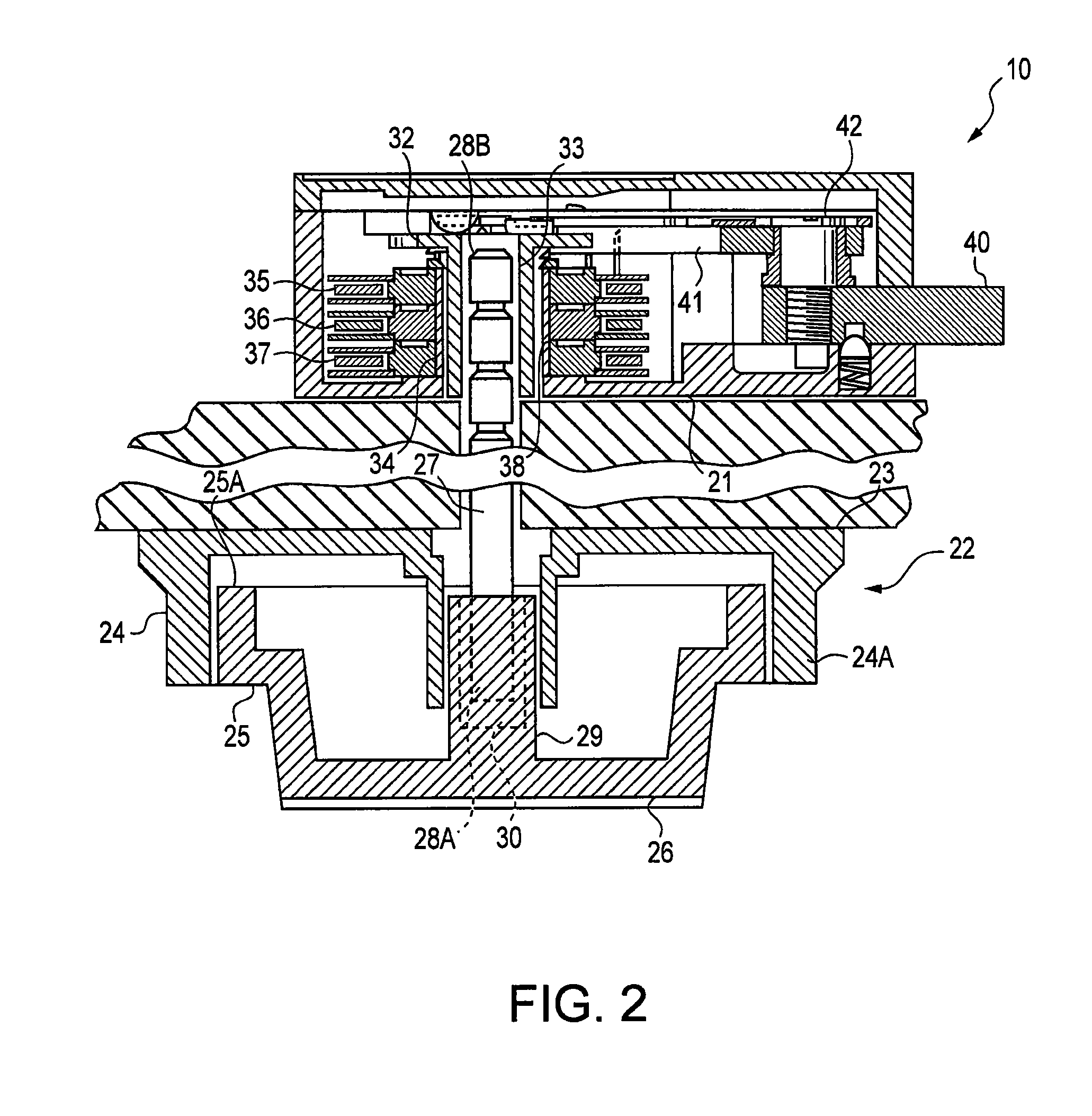
[0031]FIG. 1 is a perspective view of an exemplary lock assembly 10 in accordance with the present invention. Lock assembly 10 includes lock device 20 having mounting surface 21, mechanical dial 22 having mounting surface 23, dial ring 24 and dial portion 25, and spindle 27 extending between and coupled to lock device 20 and mechanical dial 22. Lock device 20 may be mounted against the inner surface of a door or other closure in a conventional manner, such as by mounting screws extending through screw holes near the corners of the lock housing and into the supporting door. Dial ring 24 includes a cylindrical shield 24A surrounding and shielding from view the major portion of peripheral flange 25A of dial portion 25, the shield 24A being interrupted by a sight opening 24B of suitable circumferential extent.

[0032]Dial portion 25 is supported for rotation within the forwardly opening cylindrical well of dial ring 24 defined by shield 24A, and is likewise supported for axial movement in...


PUM

PropertyMeasurementUnit
lengthaaaaaaaaaa
lengthaaaaaaaaaa
anglesaaaaaaaaaa

Abstract

In one aspect of the present invention, a lock assembly comprises a dial, a lock device, and a spindle having a spindle base and an elongate spindle shaft extending from the spindle base. The spindle shaft comprises a plurality of spindle segments having four sides and separated by a plurality of spaced apart grooves. Each of the spindle segments includes a chamfered leading edge. In another aspect of the present invention, a method of mounting a lock assembly on a mounting surface comprises positioning a dial on a first side of the mounting surface, positioning a lock device on a second side of the mounting surface, determining a distance between the first and second sides, providing a spindle including a plurality of spindle segments having four sides and separated by a plurality of spaced apart grooves, and cutting the spindle at a selected one of the spaced apart grooves.

Description

BACKGROUND OF THE INVENTION[0001]The present invention relates in general to combination locks, and more particularly to spindles for combination locks that may be easily adapted for use under various mounting conditions.[0002]Combination locks of the multiple tumbler wheel type with which the present invention is concerned usually comprise three disk-shaped tumbler wheels having a gating or notch in their periphery and spaced side-by-side on a cylindrical tumbler post projecting inwardly of the lock housing. One of the tumblers, either the forwardmost or rearmost of the three, typically is driven by a drive pin projecting toward the tumbler from a rotatable driving cam which directly engages a stop on the tumbler or a rotary fly washer which in turn engages such a tumbler stop to provide a lost motion driving connection. The remaining tumblers are driven by an adjacent tumbler in the direction of the driving cam through a similar lost motion driving connection. The driving cam has ...

Claims


Application Information

Patent Timeline
Patent Type & Authority Patents(United States)
IPC IPC(8): E05B15/00
CPCE05B37/08E05B17/0062Y10T29/49826E05B63/04Y10S292/60E05B63/006Y10T70/7401Y10T70/7949Y10T70/8838Y10T292/59Y10T292/93
Inventor GARTNER, KLAUS W.
Owner LEXAM SECURITY PROD
Why Eureka
Try Eureka