
Automotive drive train and method for reducing chatter in the same

a technology of drive train and transmission brake, which is applied in the direction of electric energy vehicles, vehicle sub-unit features, toothed gearings, etc., can solve the problems of only reducing the chatter of transmission brakes, affecting the effect of fuel saving operations, and affecting the damping of power trains

Inactive Publication Date: 2010-03-02
SCHAEFFLER TECH AG & CO KG
View PDF16 Cites 26 Cited by
  • Summary
  • Abstract
  • Description
  • Claims
  • Application Information

AI Technical Summary

Benefits of technology

The present invention provides a method and device for reducing chatter in a vehicle power train. The invention uses an electric motor to actively damp chatter by transmitting a torque to the rotating component of the power train. This torque can be modulated to effectively attenuate the chatter in both directions. The electric motor can also be used as a drive motor for the vehicle, reducing fuel consumption and allowing for a smaller combustion engine. The invention uses a high-pass filtering of the rotation speed signal to detect the chatter and a control signal to the electric motor is generated accordingly. The electric motor is connected to the control and regulating device through an actuating device, and the control and regulating device is designed to drive the rotating component when there is a chatter component with decreasing speed and to retard it when there is a chatter component with increasing speed. The invention can thus actively damp chatter and make the power train more stable and efficient.

Problems solved by technology

The chatter is caused by a negative friction coefficient gradient of the clutch, which makes the damping in the power train negative.
The vibrations are converted by the drive wheels of the motor vehicle into longitudinal vibrations, and are experienced as unpleasant by the vehicle occupants.
The transmission brake only makes a limited reduction of the chatter possible, however.

Method used


Image

  • Automotive drive train and method for reducing chatter in the same
  • Automotive drive train and method for reducing chatter in the same
  • Automotive drive train and method for reducing chatter in the same

Examples


Embodiment Construction

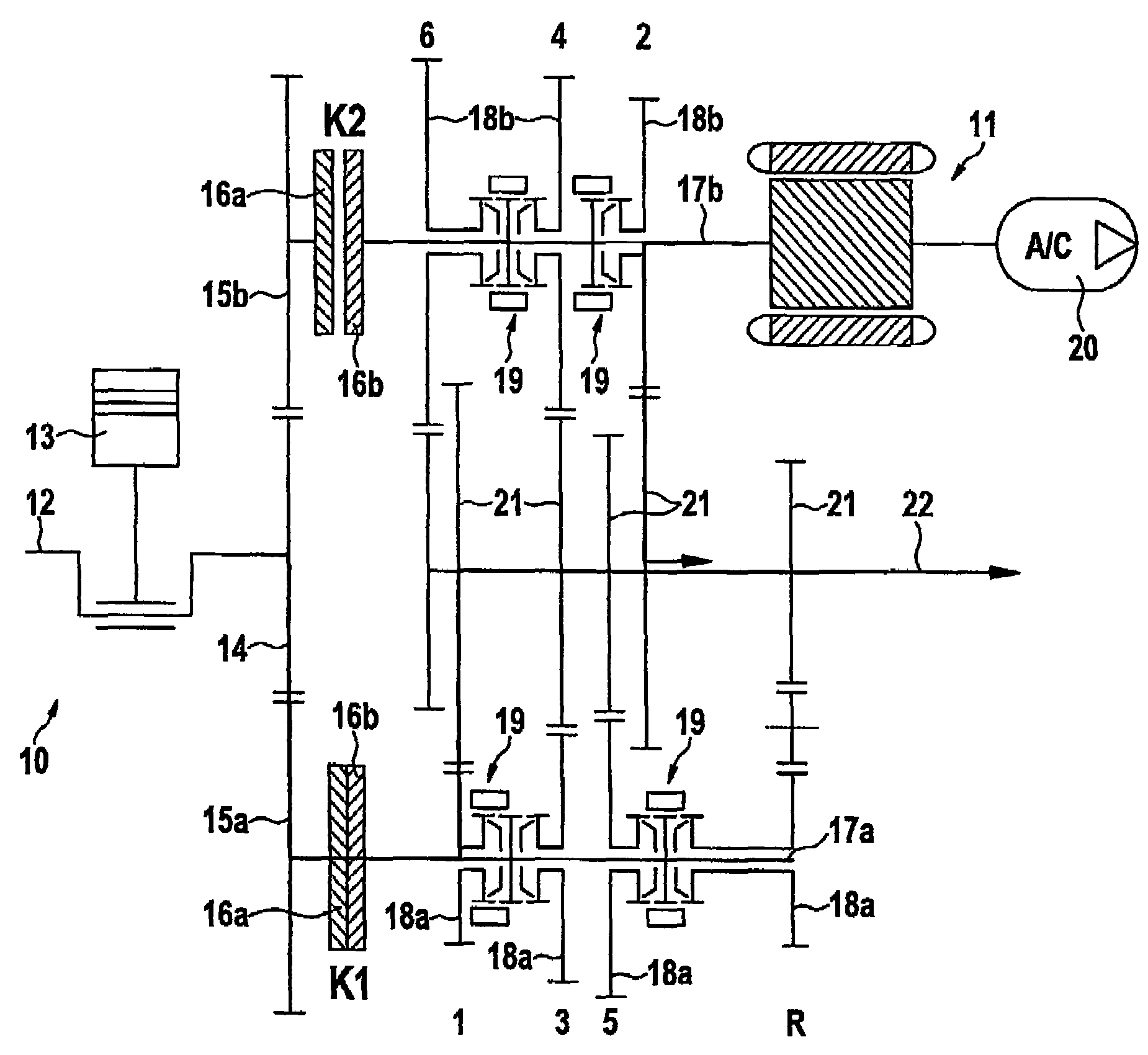
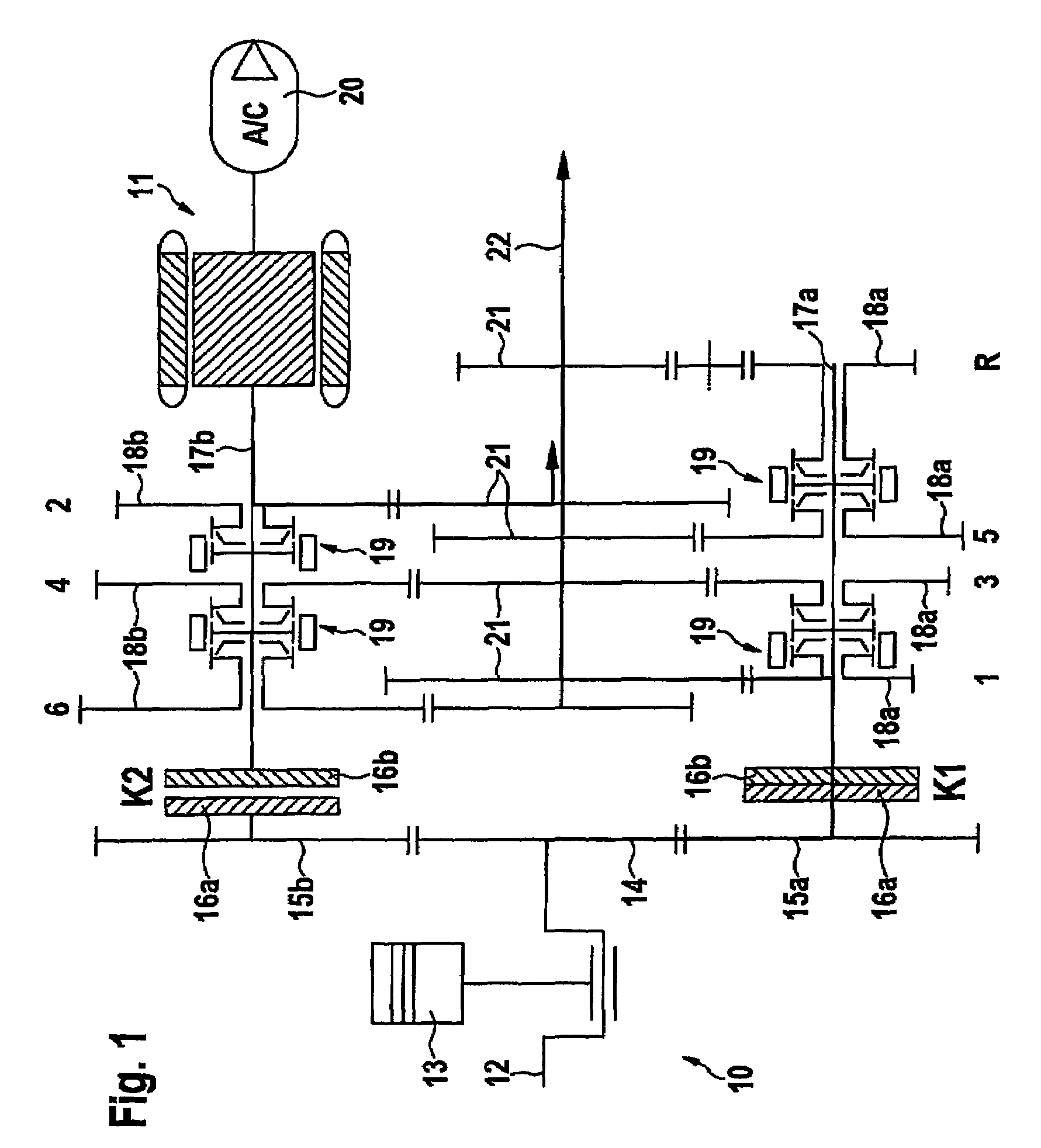
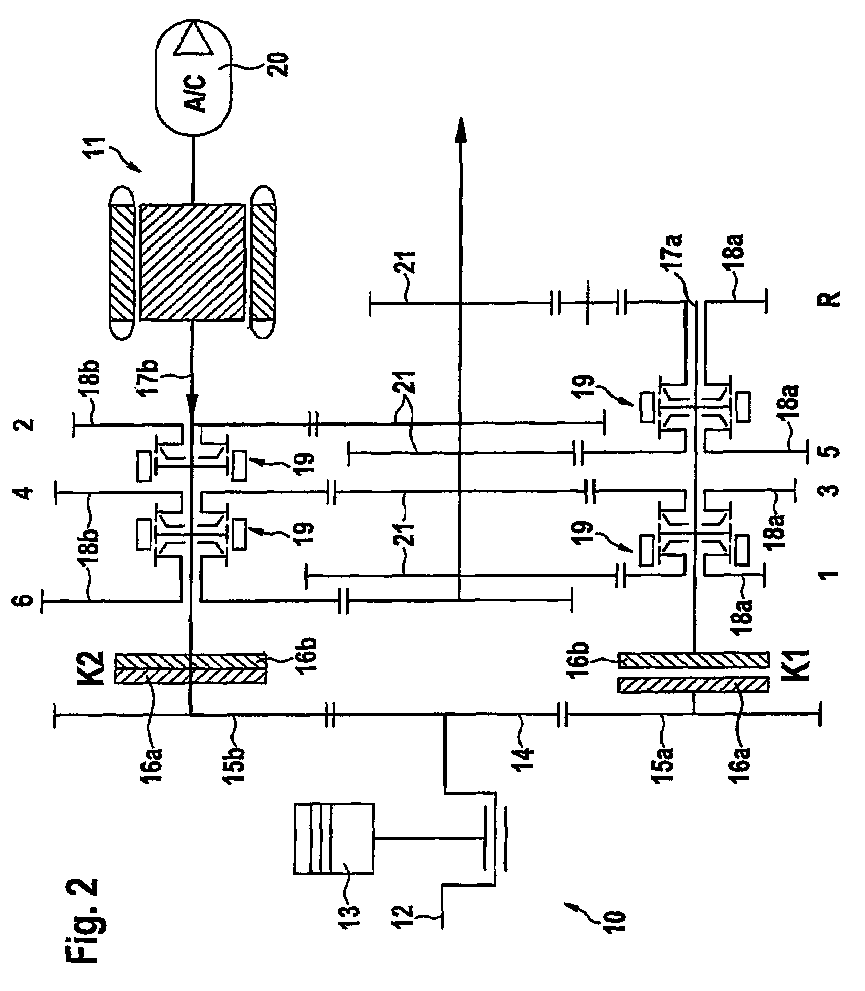
[0025]A motor vehicle power train shown schematically in FIGS. 1 and 2 has a hybrid drive with a combustion engine 10 in the form of a reciprocating piston engine and an electric motor 11 designed as a starter generator as its drive. The combustion engine 10 has a crankshaft 12 on which reciprocating pistons 13 are mounted through connecting rods; the reciprocating pistons are situated so that they can move away from and toward the crankshaft 12 in cylinders of an engine block in a known manner. On the engine block a cylinder head is provided, which has intake and outlet valves that are actuatable by means of a control device which is not shown in further detail in the drawing. The reciprocating pistons 13, the cylinder head and the intake and outlet valves delimit combustion chambers, in which a fuel-air mixture can be ignited.

[0026]The crankshaft 12 is drive-connected with a flywheel 14, which has a ring gear that meshes with two gear wheels 15a, 15b that are situated at the circu...


PUM


Abstract

The invention relates to a method for reducing chatter in automotive drive train which comprises an internal combustion engine as the drive and a clutch device. According to the method, a rotating component of the drive train is driven by means of the internal combustion engine and the speed of the component is detected. Any chatter is also detected. When chatter occurs, an electric motor is used to transmit a torque onto the rotating component in order to actively dampen the chatter. The rotating component is driven by the electric motor for any chatter component at which the speed of the rotating component decreases and the rotating component is slowed down by the electric motor for any chatter component at which the speed of the rotating component increases.

Description

[0001]This is a continuation of prior International Application PCT / DE2006 / 002101, filed Nov. 29, 2006.[0002]The invention relates to a method for reducing chatter in a motor vehicle power train that has a combustion engine as drive and a clutch device, wherein a rotating component of the power train is driven by means of the combustion engine and the speed of rotation of the component is detected, and wherein the presence of chatter is detected. The invention also relates to a motor vehicle power train that has a combustion engine as drive, a clutch device and a device for registering the speed of rotation of a rotating component of the power train, wherein the device for detecting the speed of rotation is connected to a control and / or regulating device.BACKGROUND[0003]Such a method and such a motor vehicle power train, in which chatter induced during the slippage phase of a clutch itself occurs in the power train, are known from DE 102 44 026 A1. The chatter is caused by a negativ...

Claims


Application Information

Patent Timeline
Patent Type & Authority Patents(United States)
IPC IPC(8): B60W10/08B60K6/48
CPCB60W10/08B60W10/11B60W30/20F16H3/006B60K6/48Y10T477/26F16H3/093F16H2200/0052Y02T10/6221B60Y2400/428B60L15/20B60L15/2054B60L2240/421B60L2240/423B60L2240/441B60L2240/443B60L2240/486B60L2270/145Y02T10/72B60L50/16Y02T10/62Y02T10/64Y02T10/7072B60W2050/0052Y02T10/70
Inventor WINKELMANN, STEFANSEREBRENNIKOV, BORIS
Owner SCHAEFFLER TECH AG & CO KG
Learn More