
Electric circuit for tuning a capacitive electrostatic transducer

Inactive Publication Date: 2010-03-02
SIEMENS MEDICAL SOLUTIONS USA INC
View PDF7 Cites 15 Cited by
  • Summary
  • Abstract
  • Description
  • Claims
  • Application Information

AI Technical Summary

Benefits of technology

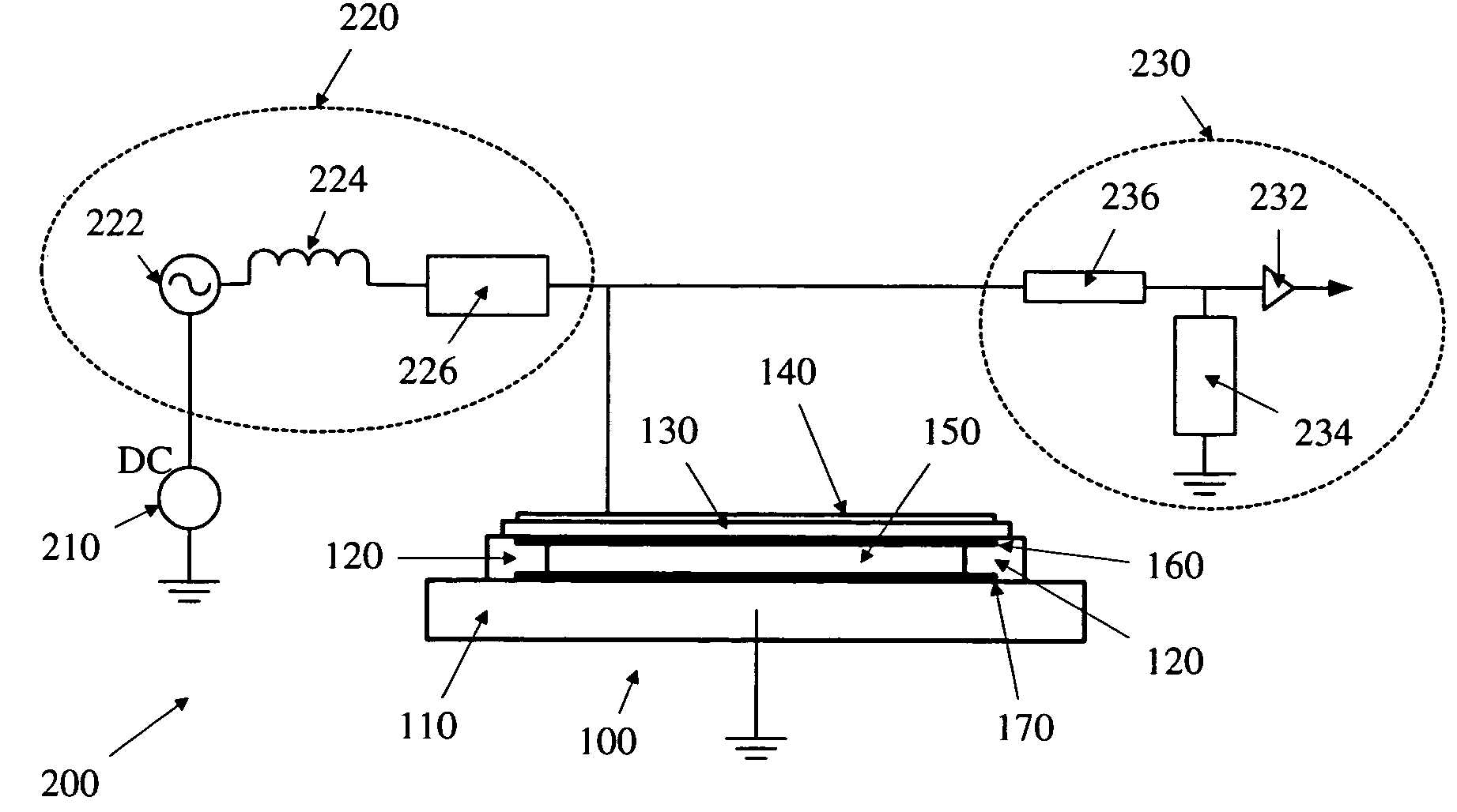
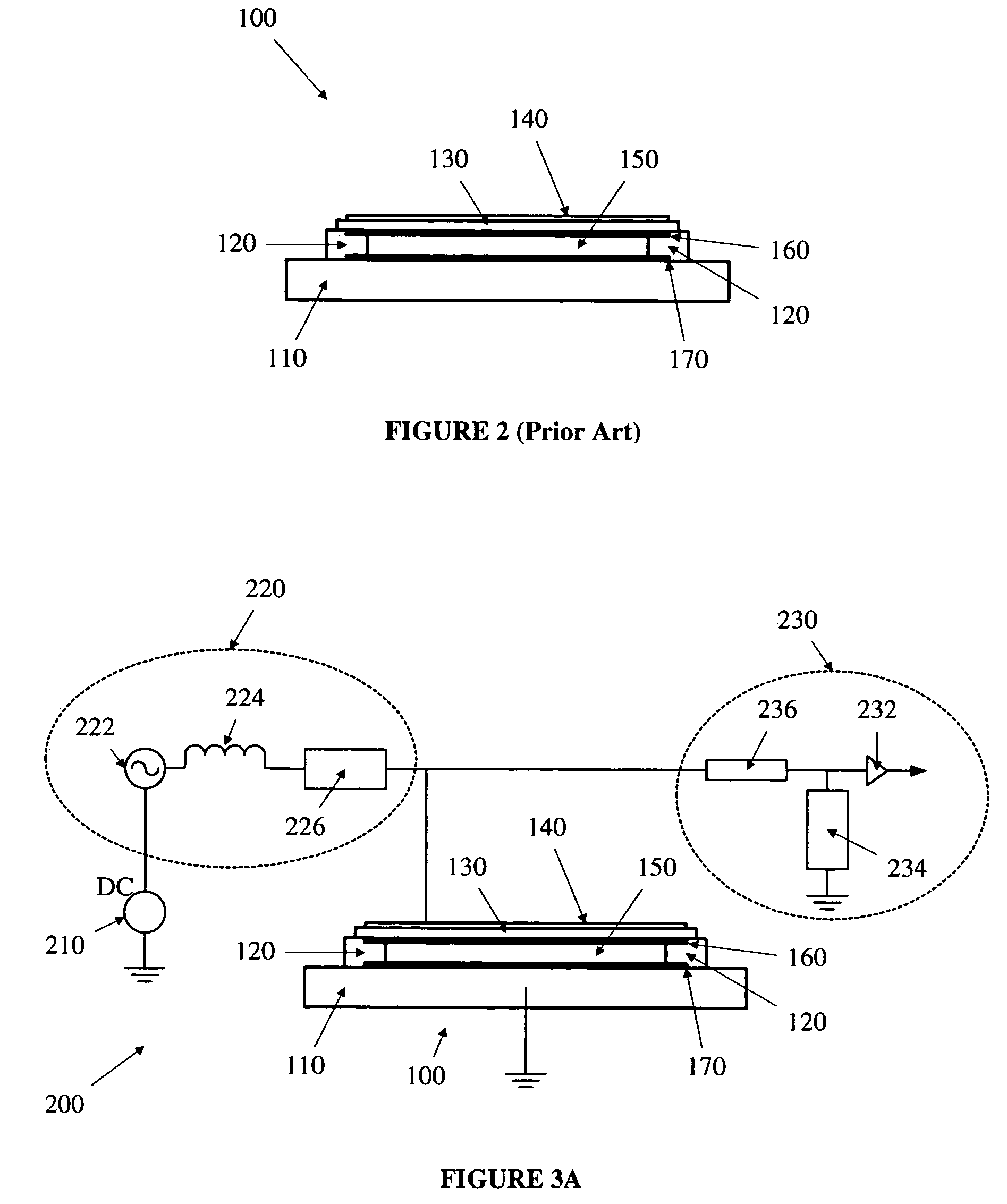
[0017]The present invention includes embodiments for tuning out, or balancing, the negative reactance of a capacitive microfabricated electrostatic transducer. The negative reactance can be tuned out, for example, by using inductive tuning, thereby making the transducer circuit more efficient. The capacitance can be balanced, for example, by inserting a negative capacitor into the receive signal path. The inductive tuning of some embodiments of the present invention result in a capacitive microfabricated electrostatic transducer that is efficient for harmonic imaging.

Problems solved by technology

These microfabricated transducers have considerable potential since the microfabrication process gives rise to low cost, highly complex structures—such as finely pitched 2D arrays of elements.
Thus, the microfabrication technology may enable 2D arrays and real-time 3D imaging, which until now has been hampered by the cost and complexity of the cumbersome, time consuming, low-yield manufacturing processes required for the ceramic-based arrays.
One drawback of the electrostatic microfabricated transducer arrays is that they substantially behave with the electrical characteristics of a capacitor.
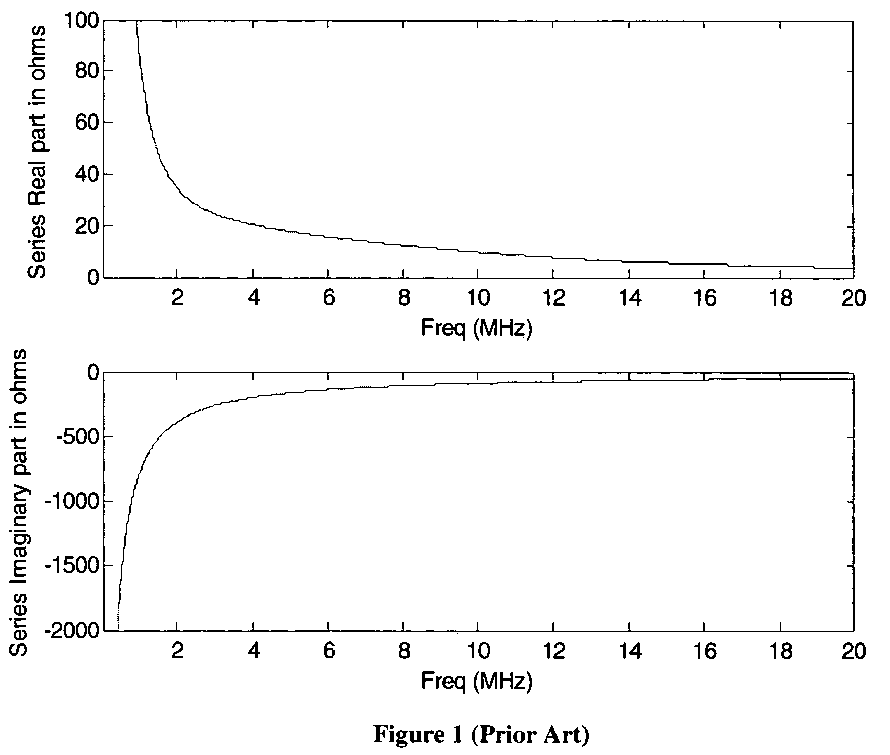
The capacitance of the microfabricated transducer introduces a negative reactance component to the overall transducer impedance, which makes the transducer inefficient.
Further still, the practical constraints of making connections to the microfabricated transducer can introduce sources of parasitic capacitance that, in addition to the transducers intrinsic capacitance, add to the negative reactance of the impedance.
The effect of a relatively large imaginary part compared to the real part of the transducer is that it can make transduction inefficient and it can cause reflections in the electrical and the acoustic domains.
Acoustic reflections are undesirable for two reasons.
First, a reflection implies that not all of the power in the acoustic wave is being converted into an electrical signal, so transduction is not efficient.
As may be evident to those skilled in the art, negative capacitance circuits can lead to unstable conditions; it is desirous to achieve a negative capacitance that follows the transducer capacitance as closely as possible without inducing instability in the probe.

Method used


Image

  • Electric circuit for tuning a capacitive electrostatic transducer
  • Electric circuit for tuning a capacitive electrostatic transducer
  • Electric circuit for tuning a capacitive electrostatic transducer

Examples


Embodiment Construction

[0034]The present invention will now be described in detail with reference to the drawings, which are provided as illustrative examples of the invention so as to enable those skilled in the art to practice the invention. Notably, the figures and examples below are not meant to limit the scope of the present invention. Where certain elements of the present invention can be partially or fully implemented using known components, only those portions of such known components that are necessary for an understanding of the present invention will be described, and detailed descriptions of other portions of such known components will be omitted so as not to obscure the invention. Further, the present invention encompasses present and future known equivalents to the components referred to herein by way of illustration.

[0035]According to an embodiment of the present invention, one aspect inserts a tuned balancing reactance into the transmit side of an electro-acoustic transducer circuit. The e...


PUM


Abstract

An electrostatic transducer circuit and method of tuning the same, in which a balancing circuit is inserted into the electrostatic transducer circuit, is described. The electrostatic transducer circuit generally includes transmit circuitry, receive circuitry, a capacitive electrostatic transducer and the balancing circuit. The balancing circuit can include, either singly or in combination, an inductance and a negative capacitance. The balancing inductance is tuned to counteract the negative reactance of the capacitive electrostatic transducer at a desired operating frequency and can be inserted into the transmit circuitry and / or the receive circuitry. The balancing negative capacitance is tuned to counteract the capacitance of the capacitive electrostatic transducer and can be inserted into the receive circuitry and / or the transmit circuitry. The transmit circuitry can be isolated from the receive circuitry, and vice versa, once the balancing circuit has been inserted. Isolation can be achieved by switching the electrostatic transducer circuit between transmit and receive modes of operation, or by providing separate transmit and receive electrode subsets.

Description

CROSS-REFERENCE TO RELATED APPLICATIONS[0001]This application is a continuation-in-part of, and claims the benefit of priority from, U.S. patent application Ser. No. 10 / 222,002 filed on Aug. 14, 2002 to John A. Hossack and entitled “Electric Circuit for Tuning a Capacitive Electrostatic Transducer” (now U.S. Pat. No. 6,726,626 B1, issued on Apr. 27, 2004), which is fully incorporated herein by reference for all purposes.BACKGROUND OF THE INVENTION[0002]1. Field of the Invention[0003]The present invention generally relates to the field of electro-acoustic transducer circuits. More specifically, the present invention relates to tuning circuitry for capacitive electrostatic microfabricated electro-acoustic transducers.[0004]2. Description of the Related Art[0005]An electro-acoustic transducer is an electronic device used to emit and receive sound waves. These transducers are used in medical imaging, non-destructive evaluation and other applications. Ultrasonic transducers are electro-a...

Claims


Application Information

Patent Timeline
IPC IPC(8): A61B8/00A61B8/14B06B1/02
CPCB06B1/0292A61B8/4483G01S7/52079
Inventor HOSSACK, JOHN A.BYMASTER, BRETTLADABAUM, IGALWAGNER, PAUL A.DAFT, CHRISTOPHER M. W.
Owner SIEMENS MEDICAL SOLUTIONS USA INC
Learn More