
Cross hatched metrology marks and associated method of use

a technology of cross-hatched metrology and associated methods, which is applied in the direction of instruments, measurement devices, photomechanical treatment, etc., can solve the problems of large target sizes, cross talk, and large target sizes

Active Publication Date: 2010-03-02
KLA TENCOR TECH CORP
View PDF10 Cites 38 Cited by
  • Summary
  • Abstract
  • Description
  • Claims
  • Application Information

AI Technical Summary

Benefits of technology

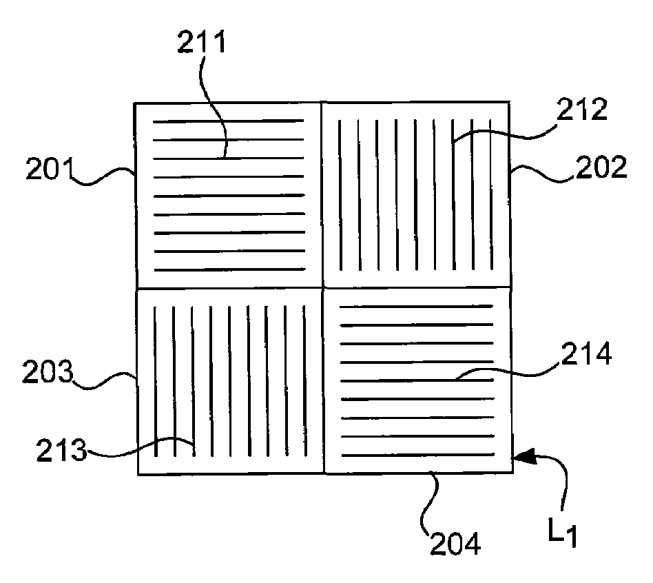
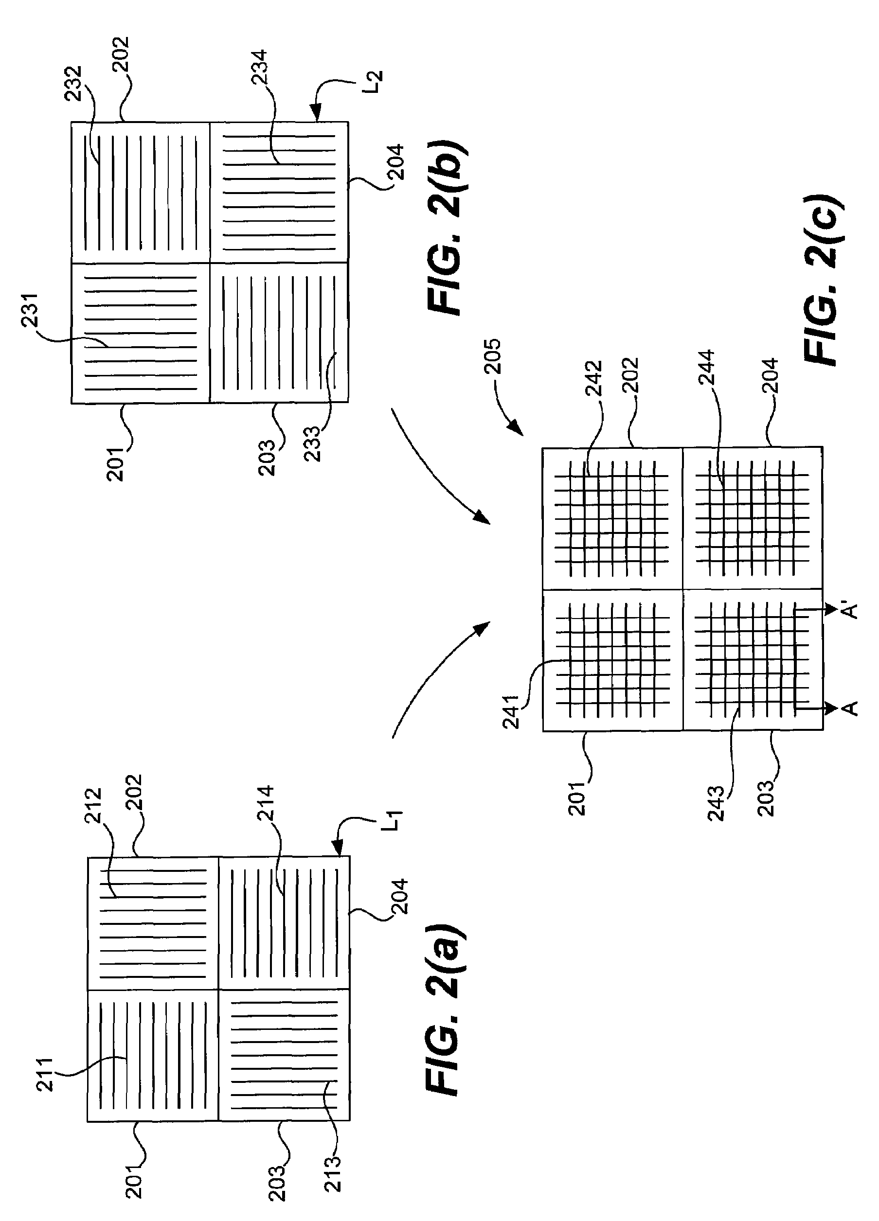
"The present invention provides a method for fast bitmapping memory instances in a semiconductor IC die. This is achieved through the use of a cross hashed overlay metrology mark that includes a substrate with multiple target regions. The mark includes a first layer with parallel periodic features arranged to form a first grating and a second layer with parallel periodic features arranged to form a second grating. The periodic features of the second grating are oriented substantially orthogonal to the periodic features of the first grating. The mark also includes a second layer above the first layer with parallel periodic features arranged to form a third grating, which is in substantial registry with the first grating. The mark also includes a fourth layer with parallel periodic features arranged to form a fourth grating, which is above and in substantial registry with the second layer. The method involves illuminating the cross-hashed metrology mark and capturing and processing the imaging signal to obtain overlay metrology information. The invention provides a faster and more efficient way to measure the alignment accuracy of memory instances in semiconductor IC dies."

Problems solved by technology

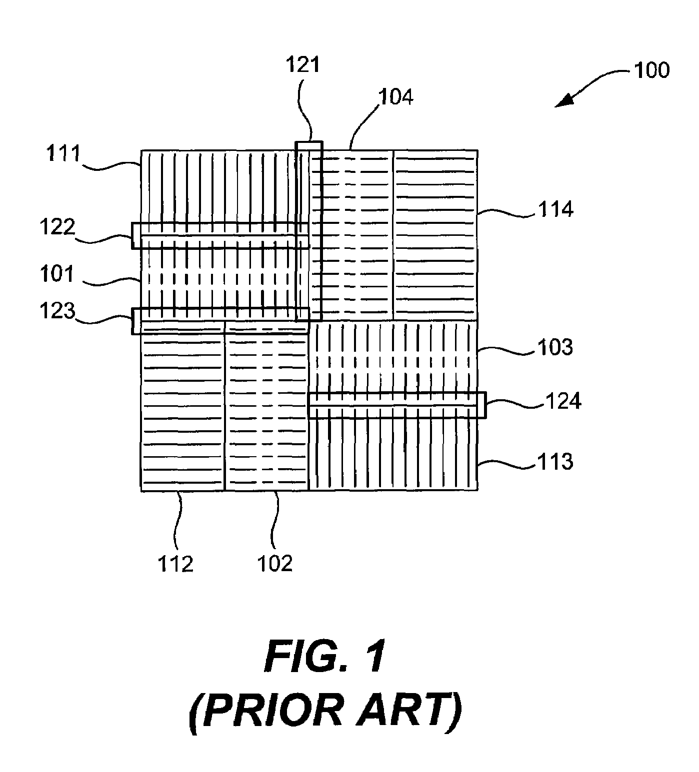
Such targets are quite large and are not easily adaptable to the constant need in the art of implementing smaller and smaller targets.
One problem inherent in the side-by-side imaging target 100 is that such targets are large, commonly being in the range of about 20 μm×20 μm to about 40 μm×40 μm in size.
Moreover, because the gratings are adjacent to one another they very susceptible to cross talk from adjacent gratings.
The inspector cannot illuminate the exclusion zone due to the risk of contaminating the signal.
As a consequence, such targets not only suffer from large size and risk of contamination in the signal, but also suffer from the fact that large portions of the target (the exclusion zones) cannot be used to obtain metrology measurements.
As briefly discussed, such targets have finite limits on how small they can be made (at least due to the need for the “exclusion zones”) and have less than desirable suitability for being made smaller.
Because the targets are formed in different layers, each portion of the target and each layer of the target is subject to varying optical properties which makes contrast equalization between the various layers and gratings a daunting and difficult problem not easily overcome in the present art.
Thus, such SCOL targets also suffer from finite size limitations and large exclusion zones that hinder there usage in ever smaller dimensions.

Method used


Image

  • Cross hatched metrology marks and associated method of use
  • Cross hatched metrology marks and associated method of use
  • Cross hatched metrology marks and associated method of use

Examples


Embodiment Construction

[0026]The present invention has been particularly shown and described with respect to certain embodiments and specific features thereof. The embodiments set forth hereinbelow are to be taken as illustrative rather than limiting. It should be readily apparent to those of ordinary skill in the art that various changes and modifications in form and detail may be made without departing from the spirit and scope of the invention.

[0027]In general terms the following discussion concerns methods and targeting approaches for conducting overlay metrology. Overlay metrology marks generally comprise features in two layers enabling overlay (i.e. displacement between layers) measurements to be measured. As previously indicated, conventional metrology marks have size limitations and limitation posed by the need for numerous exclusion zones. Additionally, the imaging implementations suffer from contrast equalization difficulties.

[0028]It is, however, advantageous to construct smaller metrology mark...


PUM


Abstract

The present invention is directed to novel metrology marks and methods for their use. The marks comprise cross hashed overlay metrology marks formed on a substrate including a plurality of target regions. The mark including a first grating structure formed in one layer of a target region and including a second grating structure formed in another layer of the target region. The periodic features of the first and second grating structures are oriented substantially orthogonal one another to form a cross-hatched metrology target in the target region. Additionally, the patent discloses methods of employing the metrology marks to obtain overlay metrology measurements.

Description

RELATED APPLICATIONS[0001]The present application claims priority under 35 U.S.C. § 119(e) from U.S. Provisional Patent Application No. 60 / 820,721 entitled “CROSS HATCHED METROLOGY MARKS AND USE OF SAME” filed Jul. 28, 2006, the entire disclosure of which is incorporated herein by reference for all purposes.FIELD OF THE INVENTION[0002]The invention described herein relates generally to methods and processes for conducting overlay metrology measurements on target substrates. Some example substrates on semiconductor integrated circuit substrates.BACKGROUND OF THE INVENTION[0003]In the semiconductor industry it is common to obtain overlay metrology measurements of integrated circuit (IC) fabrication substrates during fabrication to insure that they are within the necessary alignments tolerances.[0004]Such overlay metrology marks generally comprise features formed in two layers, the features configured to enable measurement of spatial displacement between features of the layers (i.e., t...

Claims


Application Information

Patent Timeline
Patent Type & Authority Patents(United States)
IPC IPC(8): G01B11/00
CPCG03F7/70633G03F7/70683
Inventor ADEL, MICHAEL E.LEVINSKI, VLADIMIRKASSEL, ELYAKIM
Owner KLA TENCOR TECH CORP
Learn More