
Searchlight

a searchlight and light technology, applied in the field of searchlights, can solve the problems of not providing a solution to the problem of being addressed towards an object or point in the sea, searchlight according to the german utility model does not compensate for the heave movement of said vessels,

Active Publication Date: 2010-03-02
APTOMAR
View PDF15 Cites 10 Cited by
  • Summary
  • Abstract
  • Description
  • Claims
  • Application Information

AI Technical Summary

Benefits of technology

"The searchlight invention is a device that can be used on a moving vessel to illuminate points on the sea surface. It is equipped with motors that can move the beam axis of the searchlight in two directions: perpendicular to the base plane and parallel to the base plane. The searchlight can also be rotated about its own axis. The control unit receives measurements from sensors on the vessel and uses them to calculate the position of the searchlight and the orientation of the vessel. Based on these calculations, the control unit sends signals to the motors to move the beam axis of the searchlight to keep it directed towards a specific point on the sea as the vessel moves. This invention allows for more precise and accurate illumination of the sea surface, even during vessel movement."

Problems solved by technology

U.S. Pat. No. 3,979,649 describes logic circuits for commanding a searchlight from two different command consoles, but does not provide a solution to the problem to be addressed towards an object or point in the sea.
Firstly the German utility model does not take into account said searchlights height above the sea level, or height or placement with respect to the vessels main axes.
If said searchlights elevation above the axis-centre of the boat is not taken into account, it will not be possible to compute said searchlights' movement if said vessel is subjected to pitch or roll movements, and thus said searchlight will not be able to keep the light directed towards the same point in the water.
Secondly the searchlight according to the German utility model does not compensate for said vessels' heave movement.
Thirdly, the German utility model does not take into account said searchlights location on said vessel with respect to said vessel main axes.
This is not practically feasible.
The utility model application is thus so rudimentary that the described method hardly may be performed in any adequate manner as it is presented without adding substantial elements, and thus would not be possible to perform for a person skilled in the art without adding substantial new elements.
This rapid movement is unsuitable during searches.
Any displacement of said cranes placement with respect to said boats mass centre will render the described calculations imprecise and thereby complicate the crane operations as described in the patent.
The background art is not able to solve the problem of directing a searchlight towards an object or a point in the sea, and maintain said illumination towards said point while the vessel bearing said searchlight simultaneously drives and performs rotational and translatory movements.

Method used


Image

  • Searchlight
  • Searchlight
  • Searchlight

Examples


Embodiment Construction

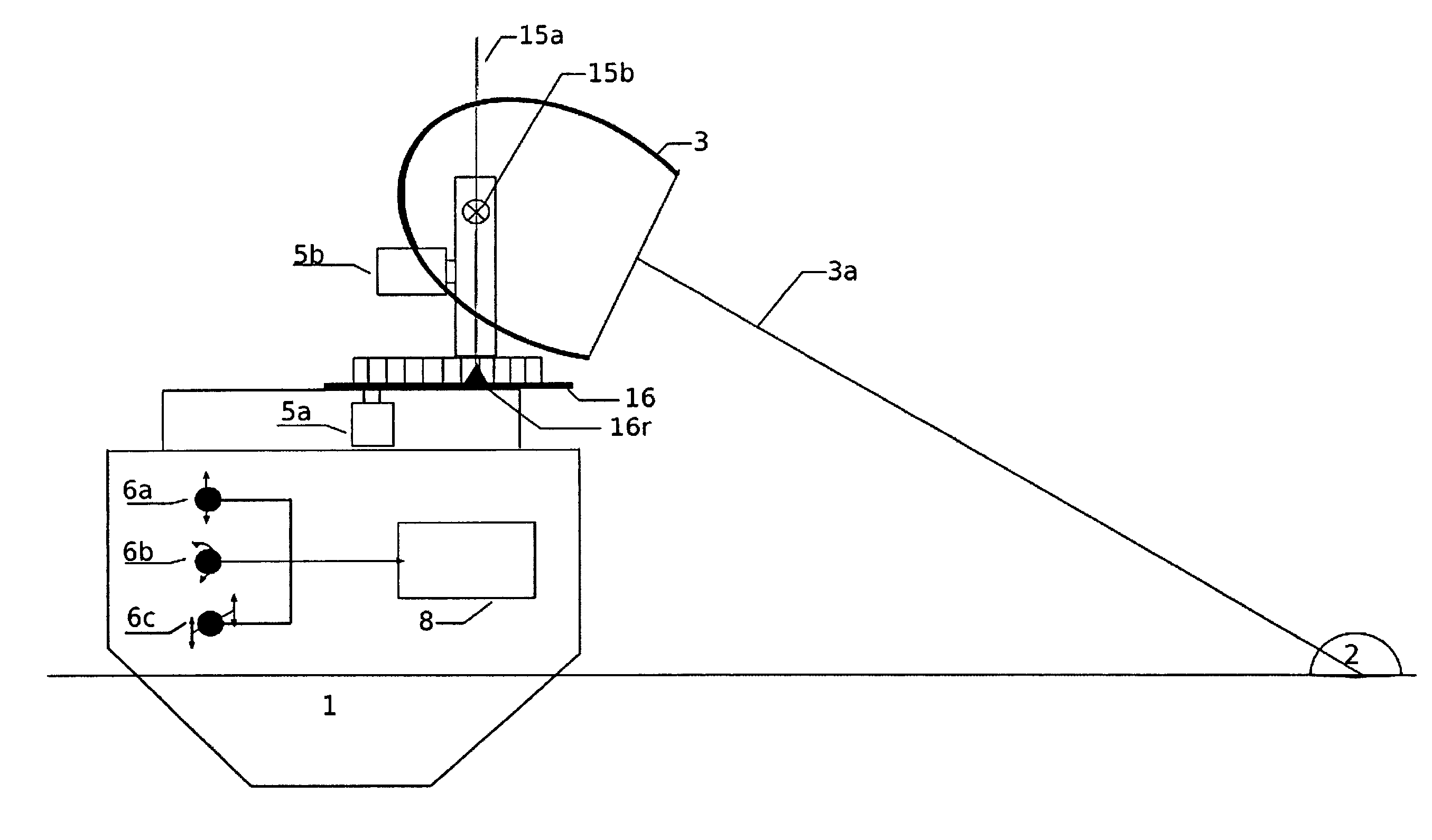
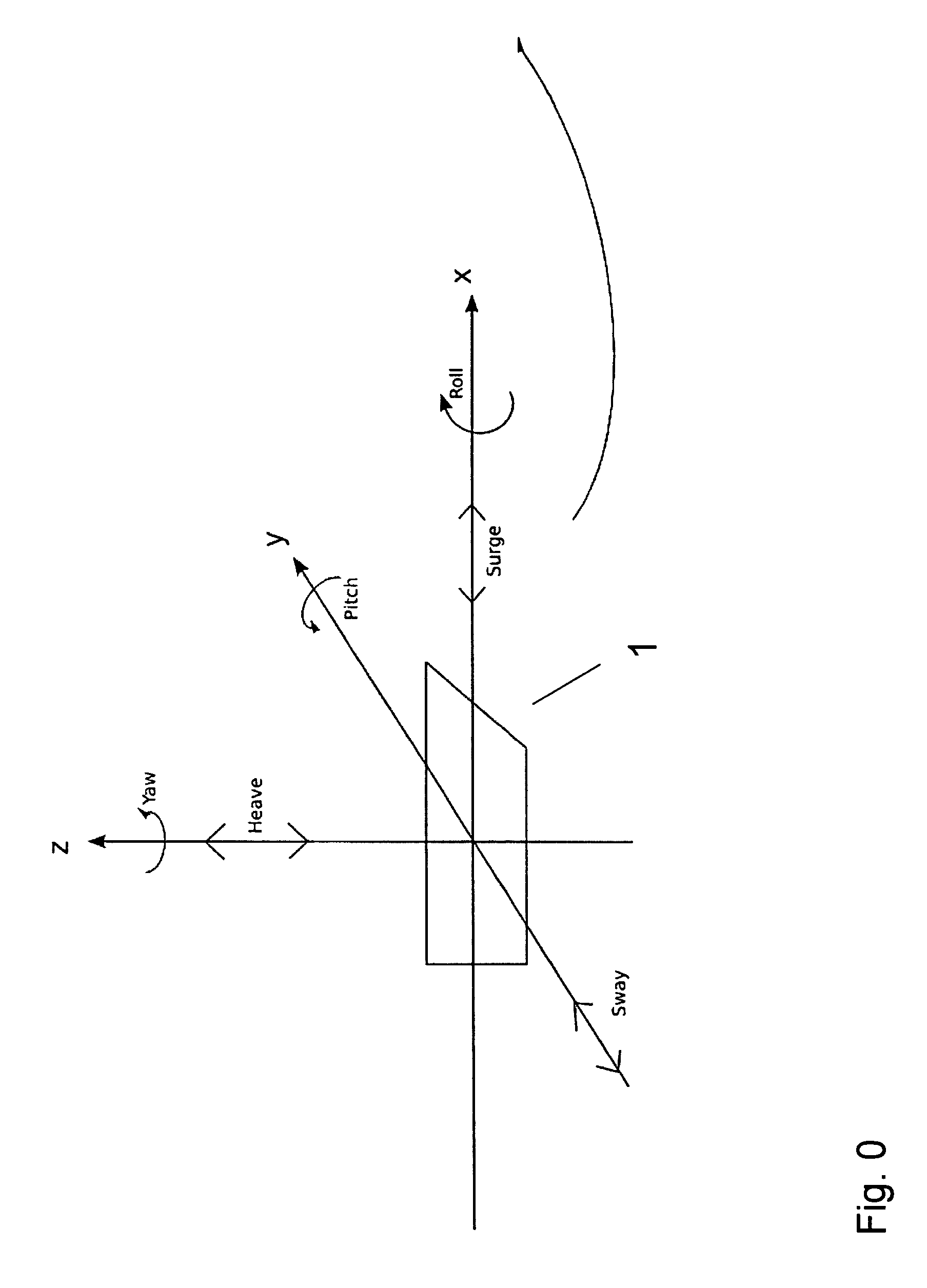
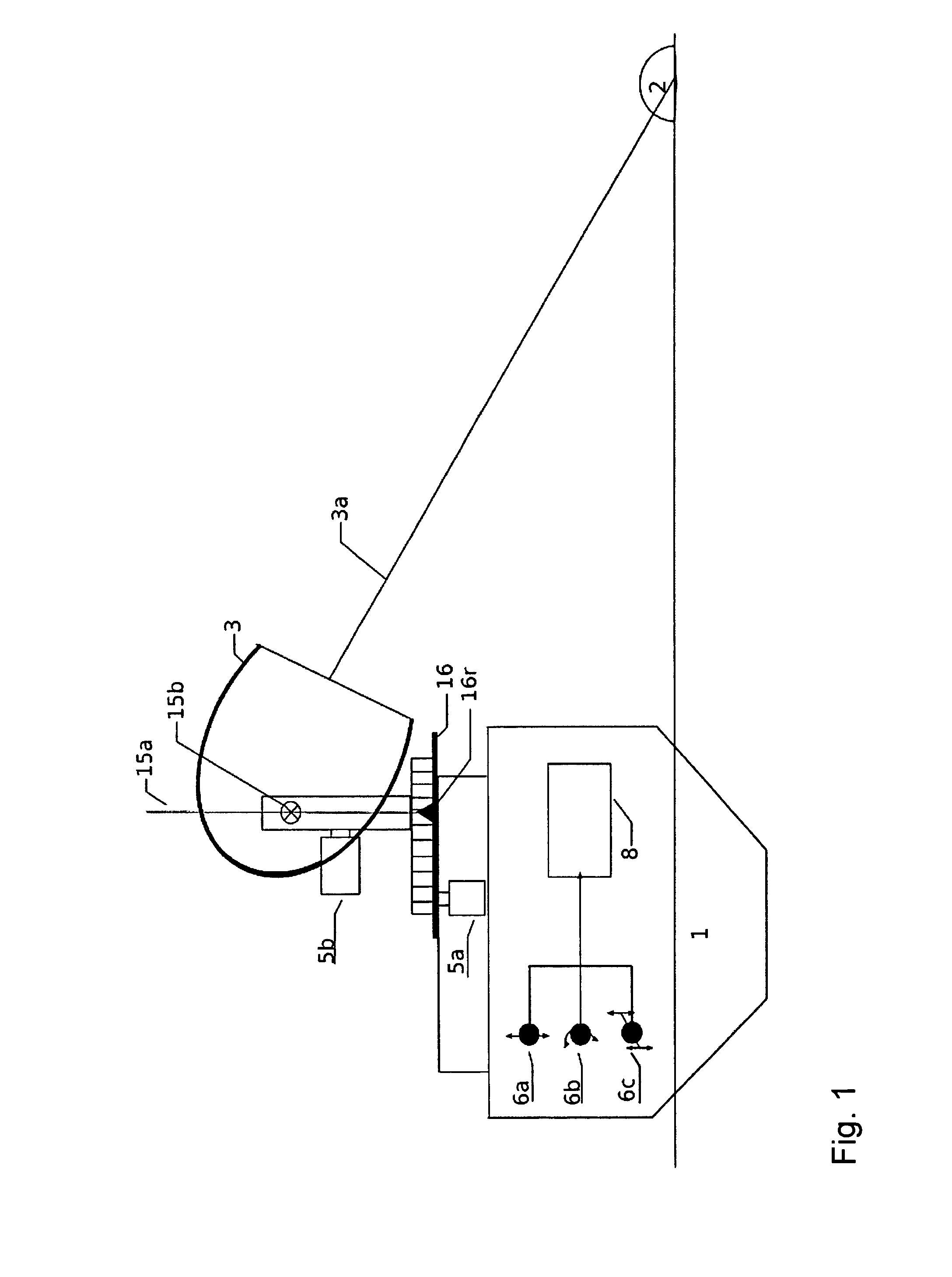
[0068]Said searchlight (3) according to an embodiment of the invention has a set-up as shown in FIGS. 13_1 and 13_2 which show elevation views and front views of a preferred embodiment of the invention. For a more detailed description of said searchlight (3) in use, reference is made to FIGS. 1 and 2 in which said searchlight (3) is shown arranged in a mounting or rack on board a vessel (1) having a height (h1) above the sea. Said searchlight (3) has a beam axis (3a), in which said beam axis (3a) is arranged for illuminating a point or an object (2p) on the surface of the sea or possibly on land.

[0069]Said searchlight (3) has two degrees of freedom with respect to said vessel (1) on which it is arranged, which are mechanically controlled and are used for controlled rotation around a perpendicular axis (15a), in which said perpendicular axis (15a) is oriented perpendicularly on a base plane (16), and in which said searchlight (3) is further arranged for controlled rotation about an a...


PUM


Abstract

A searchlight (3) on board a vessel (1) arranged for illuminating a point (2p) and maintain said point (2p) illuminated regardless of the movements of said vessel (1).

Description

INTRODUCTION[0001]When searching for persons and / or objects floating in the sea it is customary to use searchlights when the light conditions necessitate this. It is however difficult to keep the searchlight directed towards a point in the sea when the vessel is moving either by its' own power or due to weather, current and wave conditions. This is especially true as the vessel usually drives, rolls, pitches and heaves in the waves. To lose the position of the person or object one has found by means of the searchlight would be dire. There is thus a need for a searchlight which automatically compensates for the movements said vessels.[0002]The present invention describes a searchlight for use on board a moving vessel in the sea, or other moving vessel. Said searchlight is arranged for illuminating a point or position or an object which is situated on the surface of the sea, and maintain said illumination even though said vessel is moving. In a search situation, be it a rescue operati...

Claims


Application Information

Patent Timeline
Patent Type & Authority Patents(United States)
IPC IPC(8): B60L15/00B60QB63B45/02B63B45/06F21S8/00F21V21/15
CPCB63B45/02F21S8/003B63B45/06F21V21/15
Inventor SOLBERG, LARS ANDREMOR.AE BUTTED.US, JONAS AAMODT
Owner APTOMAR
Learn More