Reusable ball seat having ball support member

a technology of ball support and ball seat, which is applied in the field of ball seats, can solve the problems of reducing the likelihood that the force on the ball will push the ball through the seat or the seat will otherwise fail, and achieves the effect of reducing the inner diameter of the seat and increasing the pressur

Active Publication Date: 2010-03-09
BAKER HUGHES INC
View PDF56 Cites 79 Cited by
  • Summary
  • Abstract
  • Description
  • Claims
  • Application Information

AI Technical Summary

Benefits of technology

[0009]Broadly, ball seats having a housing, a seat, a ball support member, and a plug element such as a ball are disclosed. Typically, the ball is landed and the conduit is pressurized to a predetermined pressure. Upon pressurization of the conduit so that the ball is pushed into the seat, the seat forces a plug element support member to extend laterally, e.g., inwardly from its retracted position into the seat bore to reduce the seat inner diameter as the ball seat bore is being pressurized. In other words, the force of the ball into the seat by the pressure in the tubing causes the seat to move the plug element support member inward into the bore of the ball seat from its retracted position toward the centerline (or axis) of the bore of the ball seat and into its extended positions, thus either making contact with the previously unsupported area of the ball or otherwise distributing the force acting on the ball over a larger surface area so that the ball and seat can withstand higher pressures and / or restrict movement of the ball through the seat inner diameter as the pressure begins to deform and extrude the ball through the seat.
[0010]By being moved laterally, e.g., inwardly toward the axis of the ball seat bore, the plug element support member provides support for the ball because the resulting force against the ball caused by pressurization of the ball against the seat is spread out between the existing seat contact area and the additional force distribution area provided by the extended plug element support member. The applied pressure to the plug element support member, therefore, decreases the likelihood that the force on the ball will push the ball through the seat or that the seat will otherwise fail.
[0011]Due to the plug element support member providing additional support to the ball, the ball seats disclosed herein provide a plugging method where higher pressure can be exerted onto a seat by a lower strength ball without exceeding the ball's bearing or load strength. Further, the contact pressure resulting from having additional force distribution area provided by the plug element support members can be effectively reduced without affecting the sealability of the ball. Thus, more sizes of balls in closer increments can be utilized in various applications such as in frac ball systems. Additionally, more balls can be used because the seat inner diameter of subsequent seats can be larger due to the seat inner diameter of the seats of each ball seat in the conduit being larger. This allows more balls to go through the conduit because the seat inner diameters are larger throughout the length of conduit. Because more balls or plug elements can travel through the frac ball systems, more producible zones can be isolated by a single frac ball system.
[0012]Therefore, additional force distribution area is provided by the plug element support member that allows a greater pressure to be exerted onto the ball while keeping the original seat inner diameter the same or, alternatively, allows a larger seat inner diameter with the current pressures. The additional force distribution area also allows the contact pressure resulting from the tubing pressure onto the ball to be distributed to the standard seat contact area between the seat and the ball and the new areas provided by the plug element support member and the ball.
[0013]Furthermore, the ball seats include one or more return member, such as a coiled spring, belleville spring (also known as belleville washers), a spiral spring, or an elastomeric material, that urges the ball seat against the ball, i.e., against the fluid pressure forcing the ball into the seat. This return member can be upwardly biased so that after fluid pressurization above the ball has performed its intended function, e.g., actuation of a downhole tool, and the fluid pressurization is decreased, the return member facilitates movement of the ball seat from the set position to the run-in position. In so doing, the ball is released and allowed to be recovered, such as by floating to the surface of the well, and the bore of the ball seat is moved towards its original run-in diameter. Accordingly, the ball seat can be reused at a later date to restrict flow through the well conduit.

Problems solved by technology

The applied pressure to the plug element support member, therefore, decreases the likelihood that the force on the ball will push the ball through the seat or that the seat will otherwise fail.

Method used


Image

  • Reusable ball seat having ball support member
  • Reusable ball seat having ball support member
  • Reusable ball seat having ball support member

Examples


Embodiment Construction

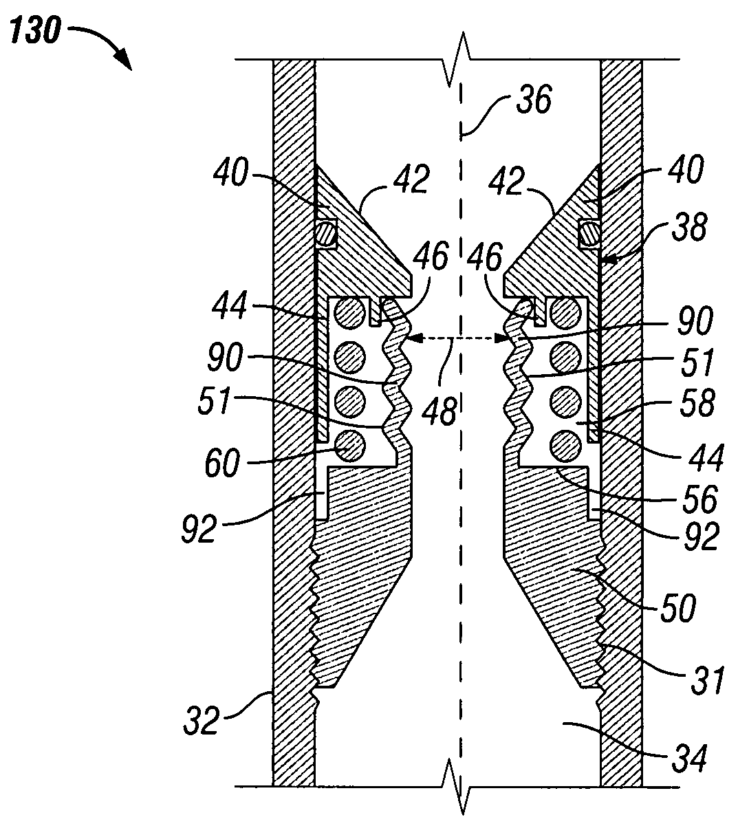
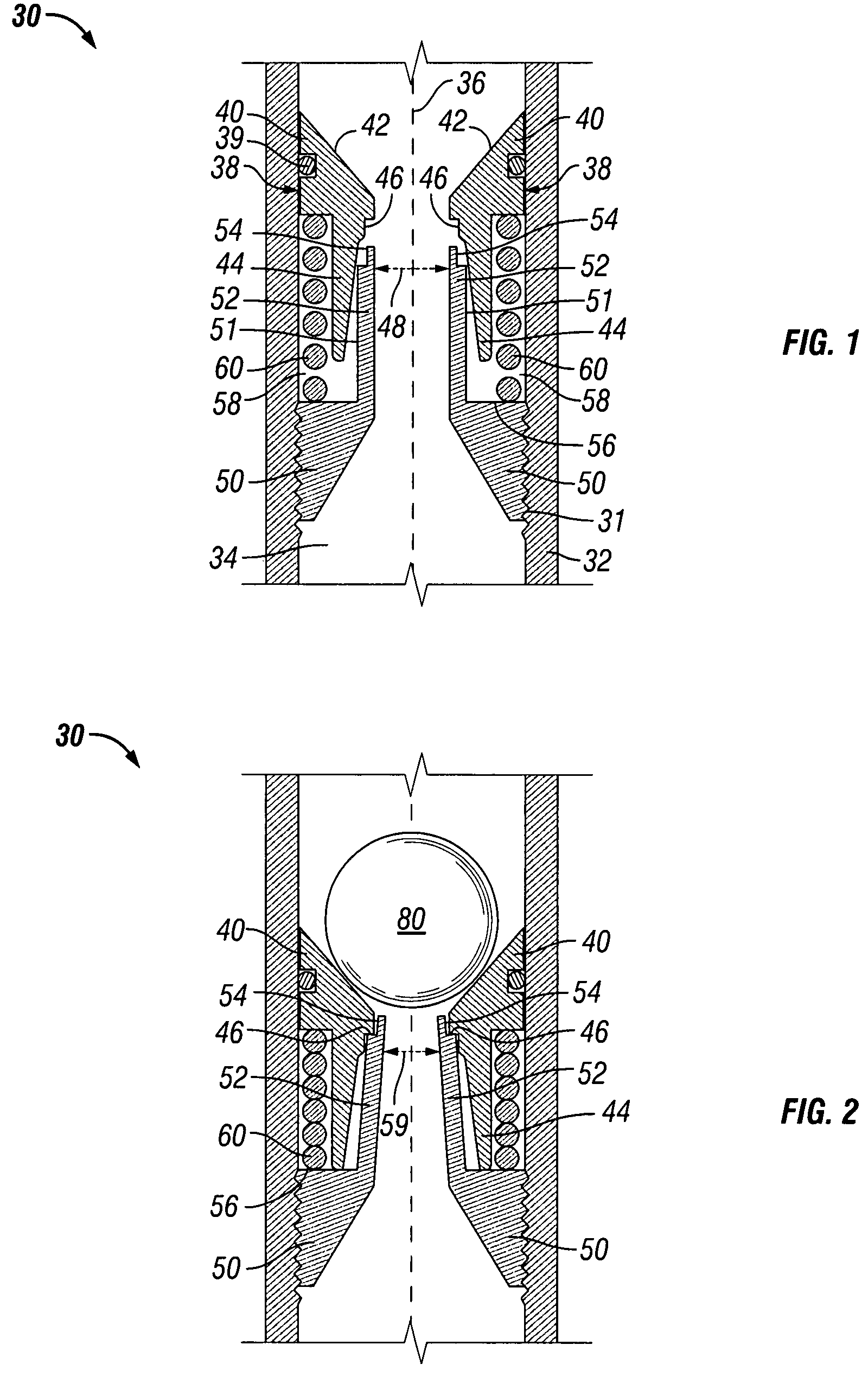
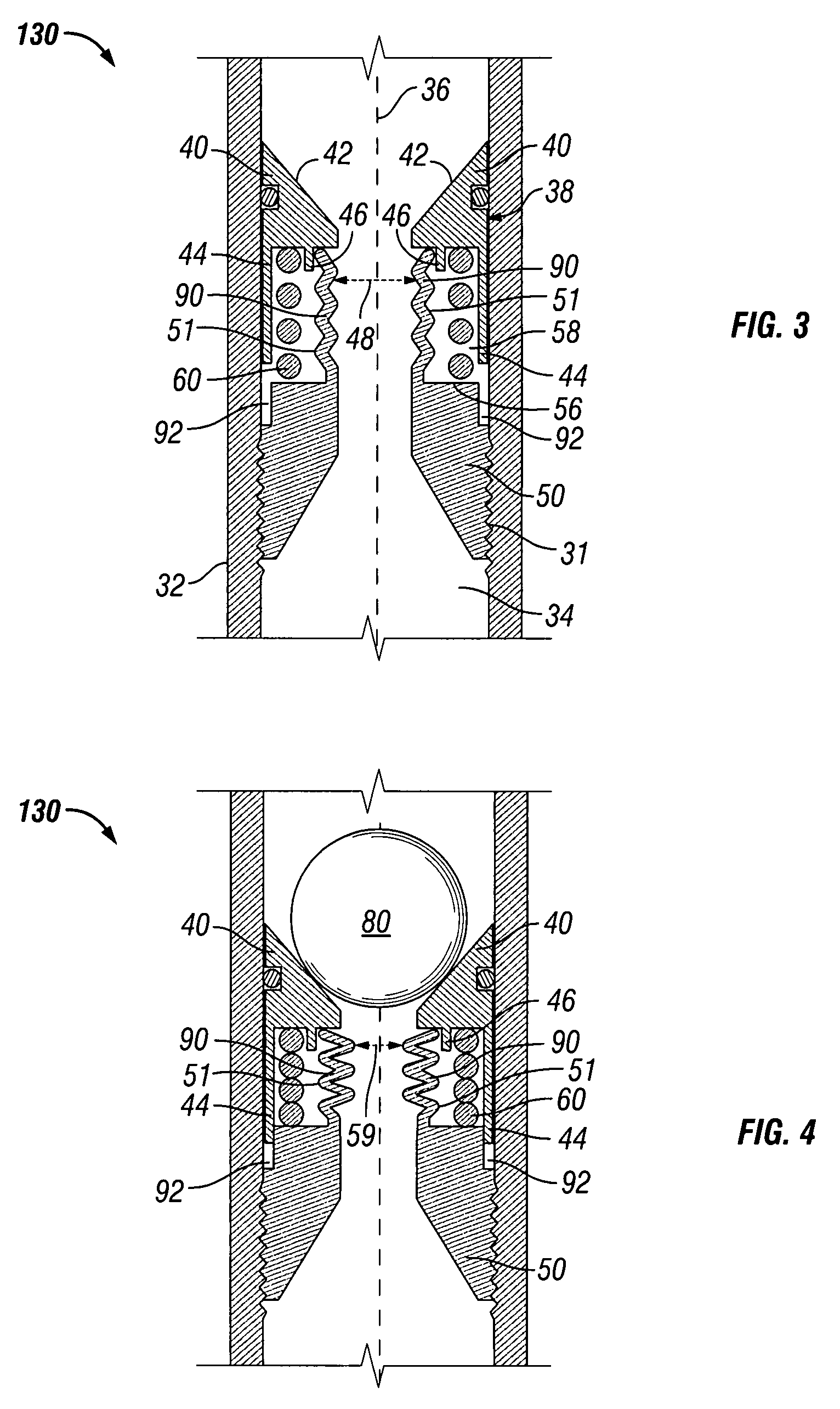
[0031]Referring now to FIGS. 1-2, in one embodiment, ball seat 30 includes a sub or housing 32 having bore 34 defined by an inner wall surface and having axis 36. Attachment members such as threads (not shown) can be disposed along the outer diameter of housing 32 or along the inner wall surface of bore 34 at the upper and lower ends of housing 32 for securing ball seat 30 into a string of conduit, such as drill pipe or tubing.

[0032]Bore 34 includes seat 38 for receiving plug element 80, shown as a ball in FIG. 2. Seat 38 includes slidable element 40 and fixed element 50. Slidable element 40 includes a housing engagement surface in sliding engagement with the inner wall surface of housing 32 (also referred to herein as a seat engagement surface) so that slidable element 40, and thus, seat 38, has a first position (FIG. 1) and a second position (FIG. 2). In one embodiment, dynamic seals 39 assist in sliding engagement of slidable element 40 with the inner wall surface of housing 32.

[...


PUM


Abstract

Apparatuses for restricting fluid flow through a well conduit comprise a housing having a longitudinal bore and a reusable seat disposed within the bore. The seat comprises a slidable element, a fixed element, a plug element support member, a seat inner diameter, and a return member to urge the slidable element toward the run-in position. The plug element support member has a retracted position when the seat is in the run-in position and an extended position when the seat is in the set position. A plug element adapted to be disposed into the bore and landed on the seat to restrict fluid flow through the bore and the well conduit is used to move the plug element support member from the retracted position to the extended position, thereby providing support to the plug element landed on the seat.

Description

BACKGROUND[0001]1. Field of Invention[0002]The present invention is directed to ball seats for use in oil and gas wells and, in particular, to reusable ball seats having a ball seat support member that provides support to the ball in addition to the support provided by the seat and a return member for returning the ball seat to its run-in position after being actuated by the ball.[0003]2. Description of Art[0004]Ball seats are generally known in the art. For example, typical ball seats have a bore or passageway that is restricted by a seat. The ball or drop plug is disposed on the seat, preventing or restricting fluid from flowing through the bore of the ball seat and, thus, isolating the tubing or conduit section in which the ball seat is disposed. As the fluid pressure above the ball or drop plug builds up, the conduit can be pressurized for tubing testing or actuating a tool connected to the ball seat such as setting a packer. Ball seats are also used in cased hole completions, l...

Claims


Application Information

Patent Timeline
Patent Type & Authority Patents(United States)
IPC IPC(8): E21B33/12E21B34/00E21B34/14
CPCE21B34/14E21B34/142
Inventor KING, JAMES G.RUDDOCK, DAVID B.
Owner BAKER HUGHES INC
Why Eureka
Try Eureka