Drop foot device

a technology of a shoe and a shoe body, applied in the field of accessories and shoes, can solve the problem of relatively inconspicuous user choice, and achieve the effect of large freedom of choi

Active Publication Date: 2010-03-09
OSSUR EURO
View PDF25 Cites 68 Cited by
  • Summary
  • Abstract
  • Description
  • Claims
  • Application Information

AI Technical Summary

Benefits of technology

[0007]It is an object of the present invention to meet at least one of the above-mentioned disadvantages. To that end, the invention provides an assembly which is characterized in that the second attachment member is provided with an attachment plate which, in use, is positioned under an upper part of the shoe. Thus, a relatively inconspicuous attachment can be realized. Further, with this attachment, it is possible to use a large number of different types of shoes in the assembly, so that the user has a large freedom of choice in determining the type of shoe desired by him / her. In particular, the user can opt for a relatively inconspicuous “normal” shoe.
[0009]According to one embodiment, it holds that the attachment plate is manufactured from a flexible material. As a result, the plate can be modeled on, for instance, the instep of the foot-drop affected foot for obtaining a favorable comfort in wearing. Preferably, it holds that the connecting plate attachment strap is provided with a Velcro closure for opening and closing the strap, so that the strap can be rapidly and fittingly attached to the leg.
[0010]According to a preferred embodiment it holds that the connecting body is substantially provided with a strip-shaped part. The strip-shaped part can be designed to be flexible for obtaining an optimal supporting characteristic. According to this supporting characteristic, the upward force applied to the foot-drop affected foot can be adapted to the relative position of the foot-drop affected foot relative to the leg in a dynamic manner which is well in line with the natural way of walking. Preferably, the strip-shaped part is provided with a first strip-shaped subpart and a second strip-shaped subpart and a closure for detachably joining together the first and the second strip-shaped subpart. As a result, the attachment strap can be disconnected from the shoe in a simple manner. When the user, while sitting down, has no need for (bottom) support or wishes to take his shoe off, the accessory can be disconnected from the shoe without the attachment plate having to be detached from the shoe.

Problems solved by technology

In particular, the user can opt for a relatively inconspicuous “normal” shoe.

Method used


Image

  • Drop foot device
  • Drop foot device

Examples


Embodiment Construction

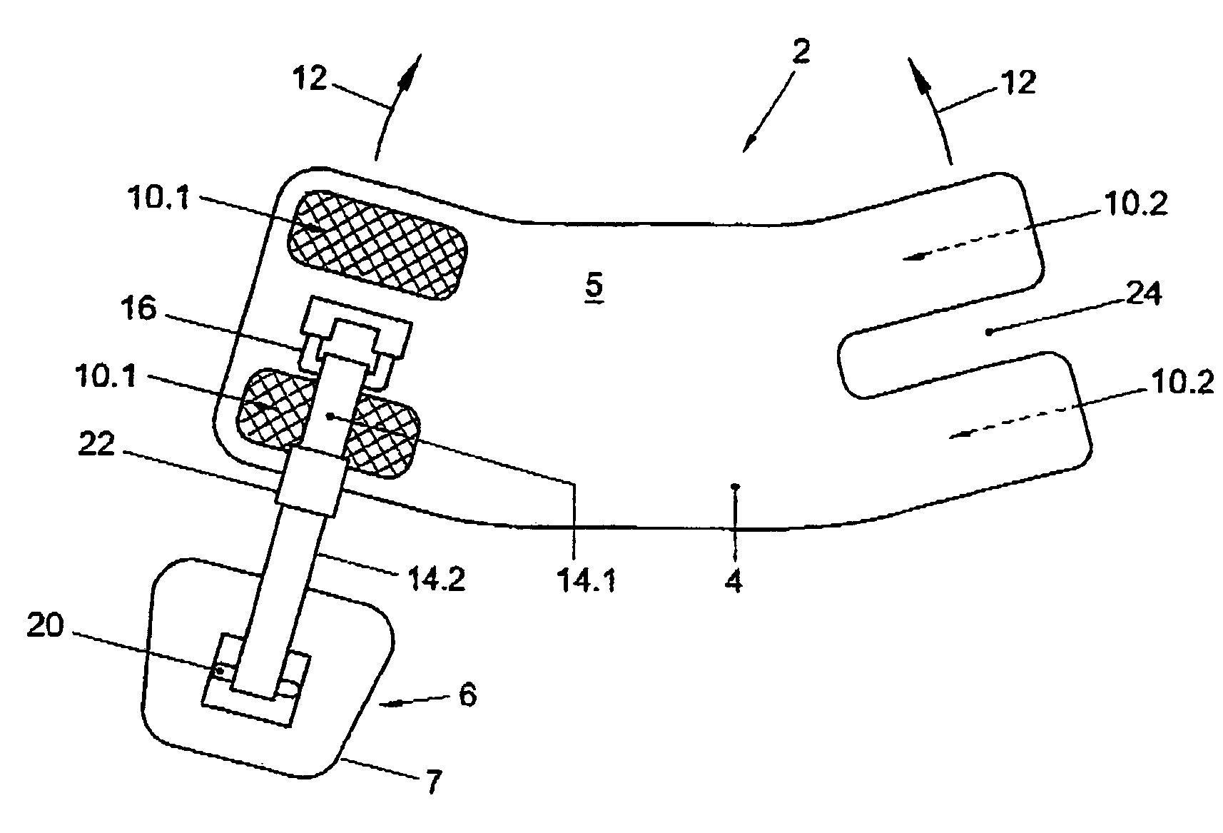
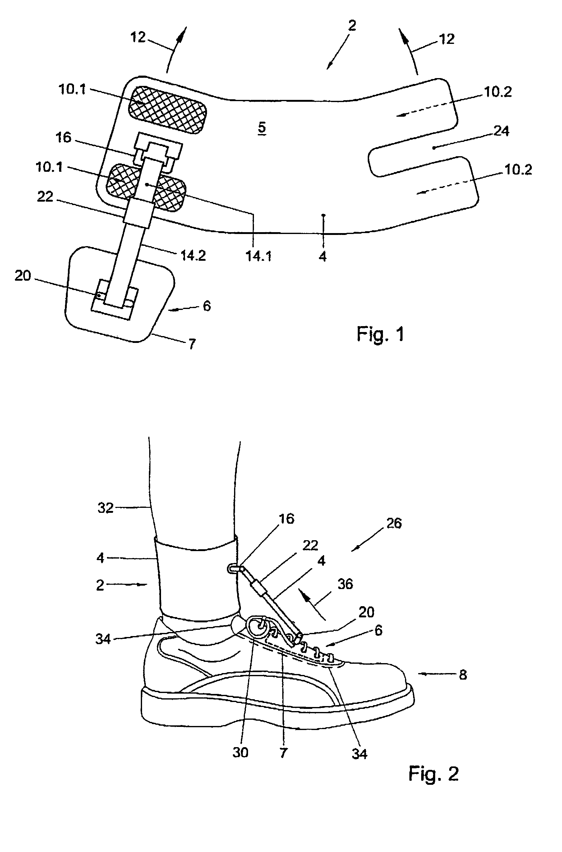
[0015]In FIG. 1, an accessory 2 is shown for supporting a foot-drop affected foot relative to a lower leg belonging to the foot such that the foot is prevented from dropping down relative to the lower leg when the foot is raised by the lower leg from a supporting surface. The accessory is provided with a first attachment member 4 for attachment of the accessory 2 to the lower leg, a second attachment member 6 for attachment of the accessory 2 to an upper side of a shoe 8 enclosing the foot-drop affected foot, and a connecting body 14 joining together the first attachment member 4 and the second attachment member 6. The second attachment member 6 is provided with an attachment plate 7 which, in use, is positioned under an upper part (such as a tongue, shoe lace or edge) of the shoe 8 (see FIG. 2).

[0016]In this example, the first attachment member4 is an attachment strap 5, provided with first Velcro parts 10.1 which can cooperate with second Velcro parts 10.2 for closing the strap 5....


PUM


Abstract

The invention relates to assembly of an accessory and a shoe for providing support to a foot-drop affected foot relative to a lower leg belonging to the foot such that the foot is prevented from dropping downwards relative to the lower leg when the foot is raised by the lower from a supporting surface, the accessory being provided with a first attachment member for attachment of the accessory to the lower leg, a second attachment member for attachment of the accessory to an upper side of the shoe and a connecting body joining together the first attachment member and the second attachment member, wherein the second attachment member is provided with an attachment plate which, in use, is positioned under an upper part of the shoe. The invention also relates to the accessory of the assembly.

Description

RELATED APPLICATION[0001]This application is a continuation of PCT International Application No. PCT / NL02 / 00298 filed May 6, 2002, the contents of which are hereby incorporated by reference in their entirety.BACKGROUND OF THE INVENTION[0002]1. Field of the Invention[0003]This invention relates to an assembly of an accessory and a shoe for supporting a foot-drop affected foot relative to a lower leg belonging to the foot such that the foot is prevented from dropping down relative to the lower leg when the foot is raised by the lower leg from a supporting surface, the accessory being provided with a first attachment member for attachment of the accessory to the lower leg, a second attachment member for attachment of the accessory to an upper side of the shoe, and a connecting body joining together the first attachment member and the second attachment member. Further, the invention relates to an accessory of the assembly for providing (bottom) support to a foot-drop affected foot.[0004...

Claims


Application Information

Patent Timeline
Patent Type & Authority Patents(United States)
IPC IPC(8): A63B15/00A61F5/01
CPCA61F5/0113Y10S482/907
Inventor KRUIJSEN, LAMBERTUS JOSEPH MARTINUSGNEITING, GUNTER
Owner OSSUR EURO
Why Eureka
Try Eureka