Anatomic vertebral cage

a vertebral cage and anatomic technology, applied in the field of spinal fusion, can solve the problems of reducing placement accuracy, prone to deformation and/or breakage, and other solutions, such as mesh cages and bone materials, to achieve the effect of enhancing positioning, minimizing back-out, and superiority

Active Publication Date: 2010-03-09
CTL MEDICAL CORP
View PDF16 Cites 79 Cited by
  • Summary
  • Abstract
  • Description
  • Claims
  • Application Information

AI Technical Summary

Benefits of technology

[0014]The cage is preferably radiolucent, being composed of a carbon fiber, but with one or more radiopaque markers to provide a certain degree of visualization. Some or all of the walls of the cage may include superior and/or inferior s

Problems solved by technology

All existing devices are prefabricated and not anatomically shaped, thus requiring the intervertebral space to be shaped to accommodate the device.
The requisite distraction devices and trial sizers interfere with the actual device fo

Method used


Image

  • Anatomic vertebral cage
  • Anatomic vertebral cage
  • Anatomic vertebral cage

Examples


Embodiment Construction

[0032]This invention improves upon the prior art by providing a cage system with significant advantages, independently and in combination. The system is capable of a custom fit while, at the same time, eliminates multiple steps, instruments and trays, and allows easier and greater access to endplate surface area. The invention can be used with autograph, allograph, and / or biologic materials.

[0033]In the preferred embodiment, the device according to the invention takes the form of a carbon fiber-faced cage. The structure is generally radiolucent, while including small radiopaque markers to provide some degree of visualization.

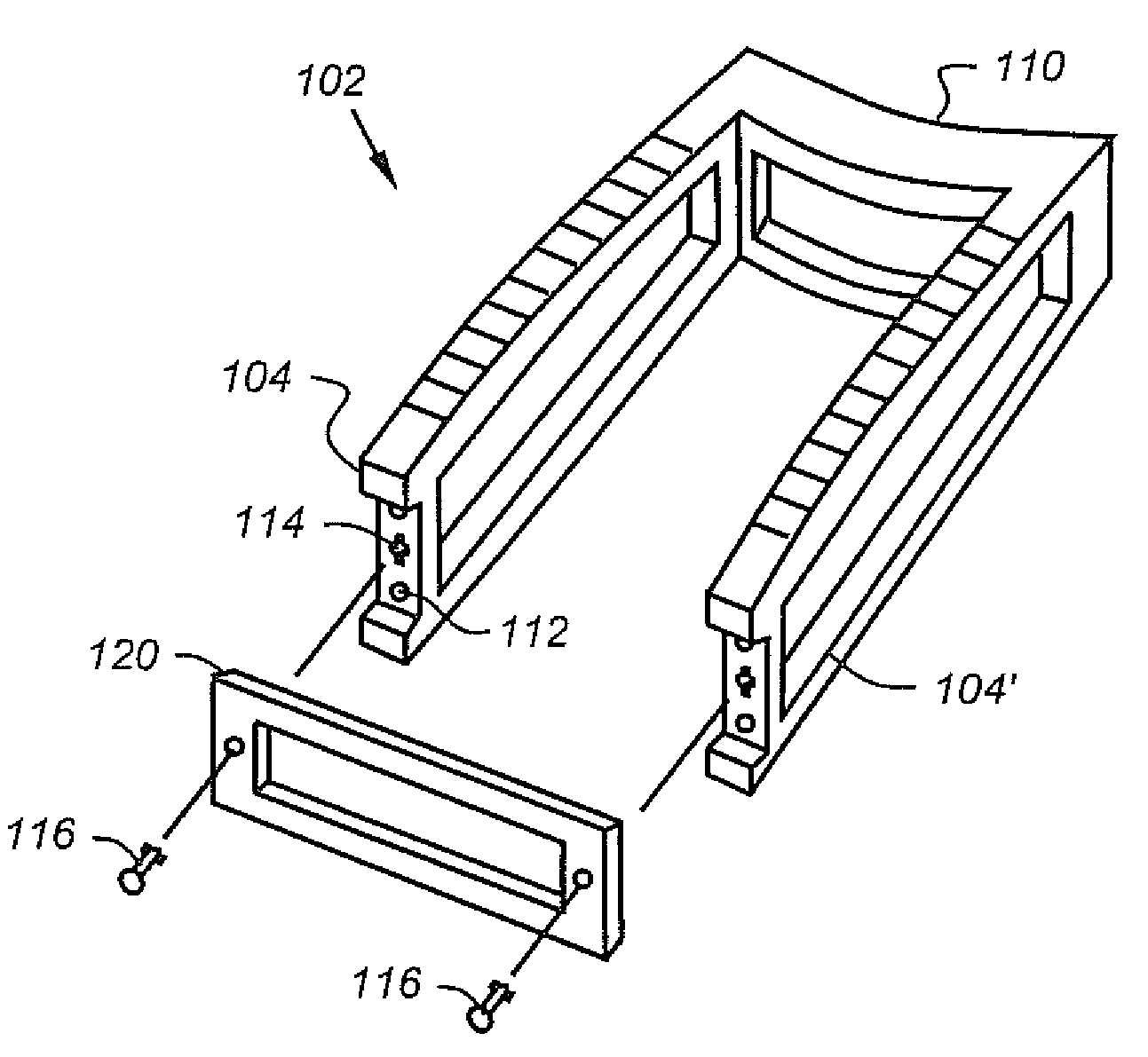
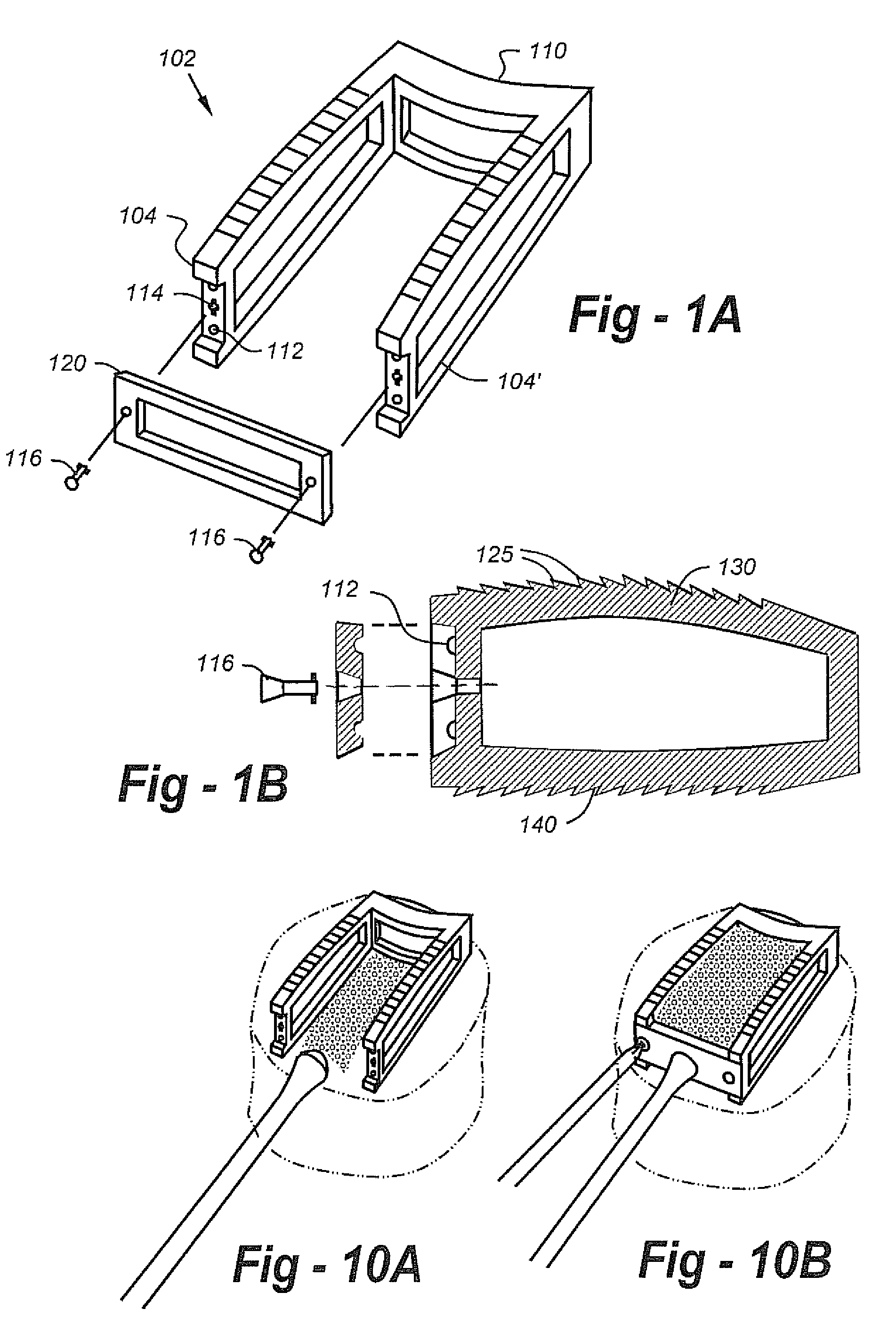
[0034]In terms of apparatus, the open-face cage 102 preferably includes contoured, dome-shaped sidewalls 104, 104′ with a flat, trapezoidal under surface, as shown in FIGS. 1A and 1B. Separate cages are provided along with tools for levels L5 to S1, which typically require a more pronounced trapezoidal shape.

[0035]Also in the preferred embodiment, the indented b...


PUM


Abstract

A spinal fusion system includes a cage with a fillable volume and removable locking gate, thereby enabling the fillable volume to be packed with graft, biologic or other materials prior to the gate being closed and locked. In the preferred embodiment, the locking gate is positioned anteriorally, though lateral, posterior, and combinations thereof are also possible. The cage is preferably radiolucent, being composed of a carbon fiber, but with one or more radiopaque markers to provide a certain degree of visualization. Some or all of the walls of the cage may include superior and/or inferior surface features to enhance positioning and/or minimize back-out, and the posterior wall may be indented to prevent neurocompression. The sidewalls of the cage may further include a recessed face with nipple indents and locking fasteners. According to a system aspect of the invention, multiple cages are provided, each being shaped differently for use at different spinal levels. For example, the cage may be larger and more trapezoidally-pronounced for the L5-S1 levels, or smaller and less trapezoidally pronounced for the T and L2 levels. The system may further including an implant introducer instrument geometrically matched to the cage, and the matched implant introducer instruments and cages may be color-coded to expedite the procedure.

Description

REFERENCE TO RELATED APPLICATION[0001]This application claims priority from U.S. Provisional Patent Application Ser. No. 60 / 388,974, filed Jun. 14, 2002, the entire content of which is incorporated herein by reference.FIELD OF THE INVENTION[0002]This invention relates generally to spinal fusion and, in particular, to an anatomic, fillable cage and instrumentation therefore.BACKGROUND OF THE INVENTION[0003]There are many surgical approaches and methods used to fuse the spine. Most involve the placement of a bone graft between the vertebrae. Supplemental hardware, such as plates, screws and cages may or may not be used, depending upon the indication.[0004]An early cage design is described in U.S. Pat. No. 4,501,269 to Bagby, entitled “PROCESS FOR FUSING BONE JOINTS.” According to the method, a hole is bored transversely across the joint and a slightly larger cylindrical basket is driven into the hole, thereby spreading the bones in resistance to the tensile forces of the surrounding t...

Claims


Application Information

Patent Timeline
IPC IPC(8): A61F2/44A61F2/00A61F2/28A61F2/30
CPCA61F2/4455A61F2/30965A61F2002/2835A61F2002/3008A61F2002/30131A61F2002/305A61F2002/30904A61F2220/0025A61F2230/0013A61F2250/0098
Inventor FALAHEE, MARK H.
Owner CTL MEDICAL CORP
Why Eureka
Try Eureka