Auxiliary drag field electrodes

a technology of auxiliary electrodes and auxiliary electrodes, which is applied in the direction of mass spectrometers, stability-of-path spectrometers, separation processes, etc., can solve the problems of delay between ions entering and exiting, slowing of ions, and other undesirable effects, so as to achieve low cost and facilitate the configuration of auxiliary electrodes.

Active Publication Date: 2010-03-09
THERMO FINNIGAN
View PDF21 Cites 64 Cited by
  • Summary
  • Abstract
  • Description
  • Claims
  • Application Information

AI Technical Summary

Benefits of technology

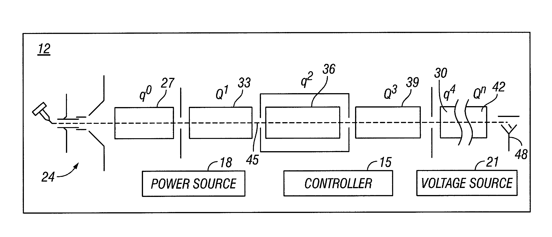
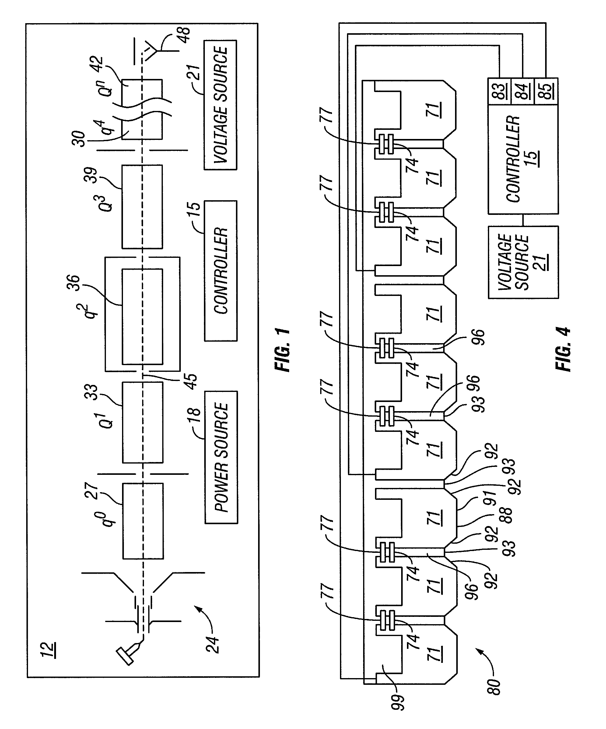
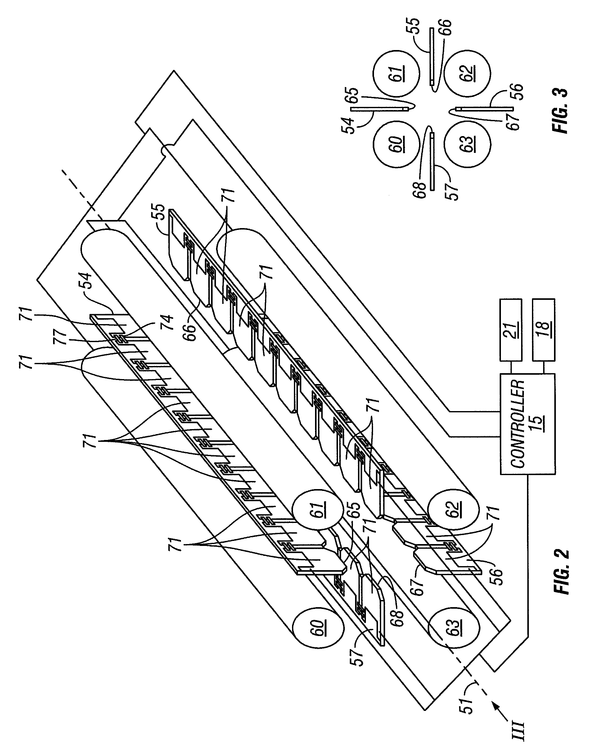
[0013]Hence, the present invention is directed to auxiliary electrodes that can urge ions axially in ion guides and collision cells. There is a need to provide these auxiliary electrodes at low cost and in a manner that makes it feasible to easily configure the auxiliary electrodes to any shape in order to match curved main electrode sets. Placement of a generally flat or low profile array of finger electrodes on a printed circuit board material enables placement of the auxiliary electrodes formed with these arrays between main RF electrodes in a multipole ion guide or collision cell. The placement can be such that radially inward edges are close to the central axis. Thus, axial voltage gradients created by the voltages applied to the array of finger electrodes can effectively move the ions through the multipole.

Problems solved by technology

However, the slowing of the ions also creates delays in ion transmission through the rod sets, and from one rod set to another.
While the focusing is desirable, the slowing of the ions is also accompanied by other undesirable effects.
Therefore, there is a delay between ions entering the ion guide and the ions reaching the mass filter just downstream.
This delay can cause problems in multiple ion monitoring, for example, where several ion intensities are monitored in sequence.
The ion clear out time (typically several tens of milliseconds) can cause tailing in the chromatogram and other spurious readings due to interference between adjacent channels when monitoring several parent / fragment pairs in rapid succession.
This required pause time between measurements reduces the productivity of the instrument.

Method used


Image

  • Auxiliary drag field electrodes
  • Auxiliary drag field electrodes
  • Auxiliary drag field electrodes

Examples


Embodiment Construction

[0027]In the description of the invention herein, it is understood that a word appearing in the singular encompasses its plural counterpart, and a word appearing in the plural encompasses its singular counterpart, unless implicitly or explicitly understood or stated otherwise. Furthermore, it is understood that for any given component or embodiment described herein, any of the possible candidates or alternatives listed for that component may generally be used individually or in combination with one another, unless implicitly or explicitly understood or stated otherwise. Additionally, it will be understood that any list of such candidates or alternatives is merely illustrative, not limiting, unless implicitly or explicitly understood or stated otherwise. It is also to be understood, where appropriate, like reference numerals may refer to corresponding parts throughout the several views of the drawings for simplicity of understanding.

[0028]Moreover, unless otherwise indicated, numbers...


PUM


Abstract

Auxiliary electrodes for creating drag fields may be provided as arrays of finger electrodes on thin substrates such as printed circuit board material for insertion between main RF electrodes of a multipole. A progressive range of voltages can be applied along lengths of the auxiliary electrodes by implementing a voltage divider that utilizes static resisters interconnecting individual finger electrodes of the arrays. Dynamic voltage variations may be applied to individual finger electrodes or to groups of the finger electrodes.

Description

BACKGROUND OF THE INVENTION[0001]1. Field of the Invention[0002]Mass Spectrometers often employ multipole ion guides including collision cells. Ion guides include a plurality of electrodes to which a variety of voltages are applied to contain or move ions radially and / or axially. The present invention relates specifically with apparatuses and methods for moving ions axially by auxiliary rods in multipole ion guides and collision cells.[0003]2. Discussion of the Related Art[0004]In tandem mass spectrometers such as triple stage quadrupole mass spectrometers, and also in other mass spectrometers, gas within the volumes defined by the RF rod sets in ion guides and collision cells improves the sensitivity and mass resolution by a process known as collisional focusing. In such a process, collisions between the gas and the ions cause the velocities of the ions to be reduced, causing the ions to become focused near the axis. However, the slowing of the ions also creates delays in ion trans...

Claims


Application Information

Patent Timeline
Patent Type & Authority Patents(United States)
IPC IPC(8): H01J49/42H05H9/02
CPCH01J49/4225H01J49/063
Inventor KONICEK, MICHAELLAND, ADRIANPERELMAN, GERSHONEARLEY, LEEHARDMAN, MARK
Owner THERMO FINNIGAN
Why Eureka
Try Eureka