Brush spring retainers

a spring retainer and brush technology, applied in the field of holders or cards, can solve the problems of non-uniform performance and life, non-standard performance and life, and elevated brush wear

Active Publication Date: 2010-03-09
WABTEC HLDG CORP
View PDF11 Cites 8 Cited by
  • Summary
  • Abstract
  • Description
  • Claims
  • Application Information

AI Technical Summary

Benefits of technology

[0005]The present invention resolves the problems created by having to provide extensive manual force to push spring brackets into heavy-duty brush holders (whether for locomotive use or otherwise). Assemblies of the invention include temporary capture mechanisms for the brush springs, allowing the springs to be retracted—and retained in a retracted position—whil...

Problems solved by technology

Moreover, the severity of the environment in which train-mounted brush holders are placed has precluded use of conventional constant-force holders for these purposes.
Instead, variable-force holders traditionally are used, notwithstanding that such holders could result in non-uniform performance and life, elevated brush wear, sparking, and increased potential for flash-over.
Signif...

Method used


Image

  • Brush spring retainers
  • Brush spring retainers
  • Brush spring retainers

Examples


Embodiment Construction

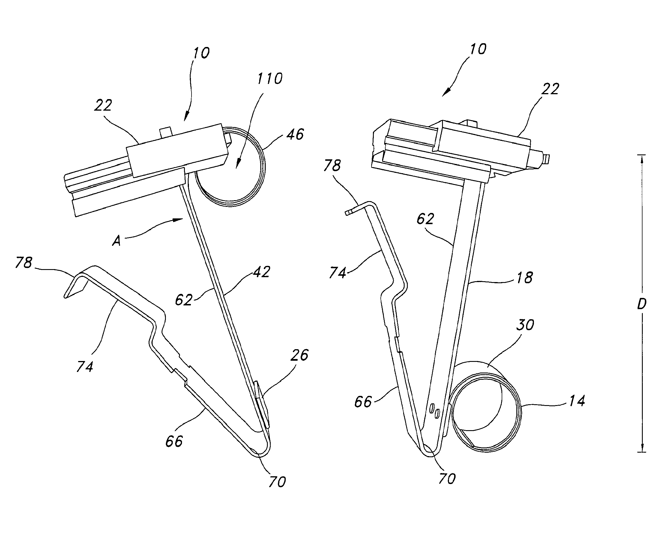
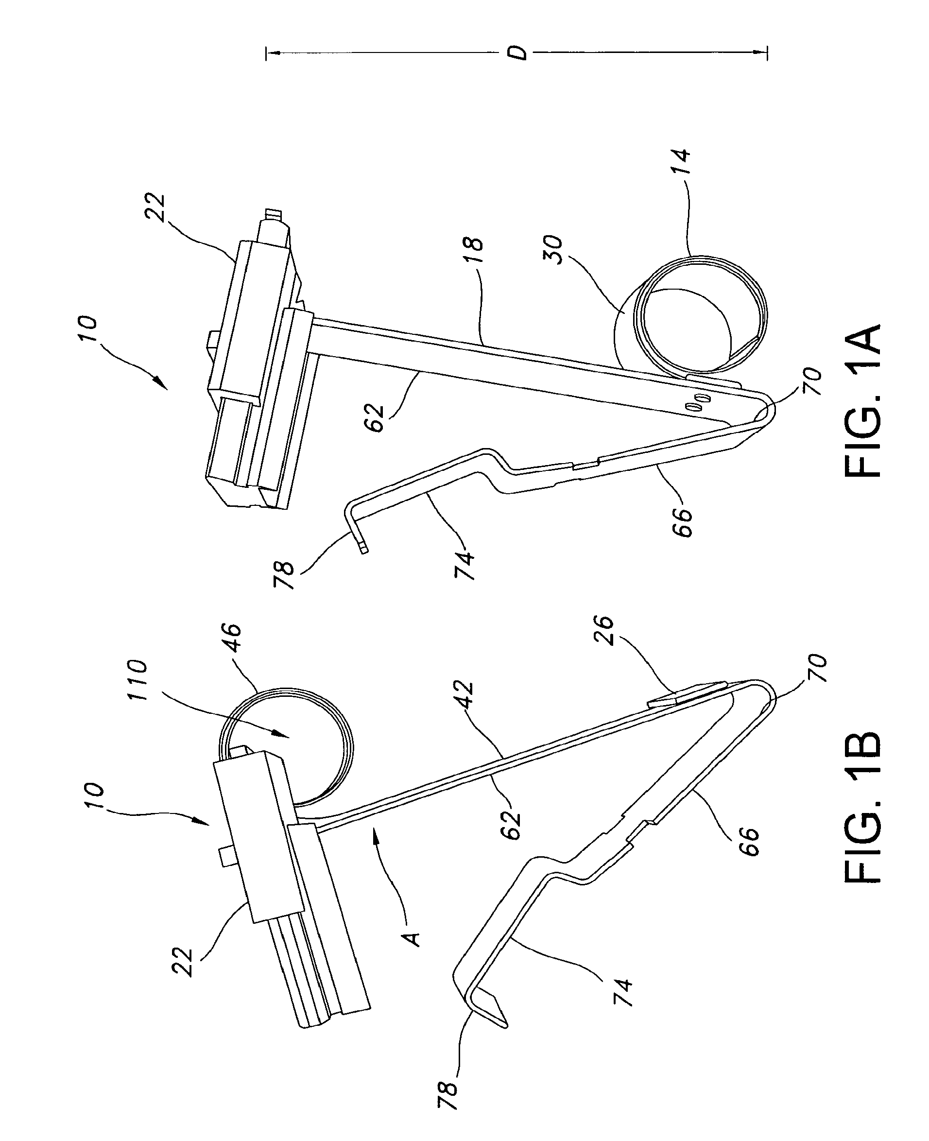
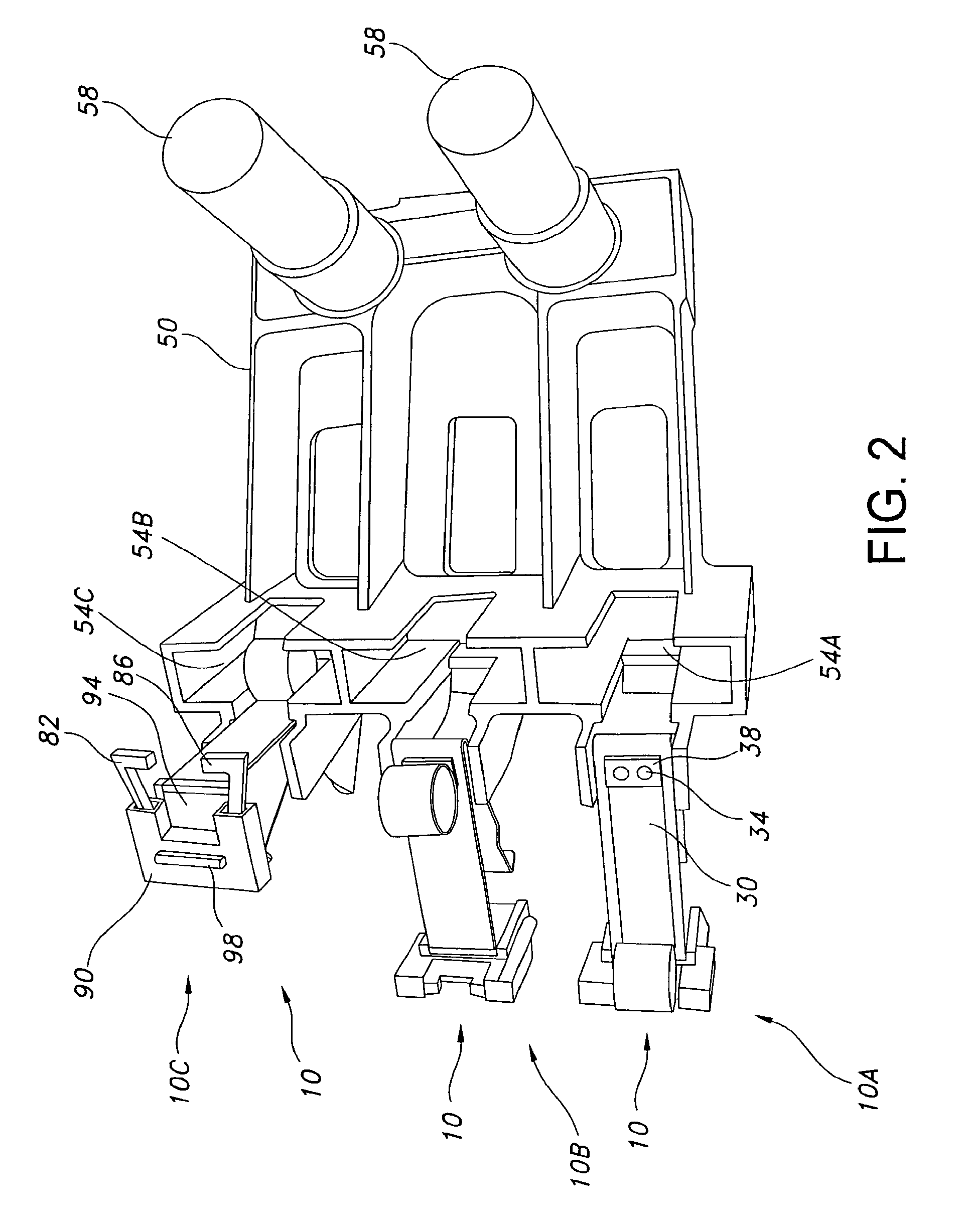
[0022]FIGS. 1A-1B detail exemplary brush spring assembly 10 of the present invention. Preferably included as part of assembly 10 are spring 14, base 18, and capture mechanism 22. Also shown in FIGS. 1A-1B are one or more fasteners 26, which function to attach end 30 of spring 14 to base 18. Although rivets 34 and bar 38 (see FIG. 2) constitute preferred fasteners 26, those skilled in the art will recognize that numerous other fastening mechanisms may be used instead.

[0023]FIG. 1A details metallic spring 14 in a rolled, unretracted position. In this rolled position, it is available to contact and bias an associated brush toward a commutator surface. Further, because of its construction, spring 14 may provide relatively constant bias force to the brush, avoiding problems related to utilizing non-constant-force springs.

[0024]By contrast, FIG. 1B illustrates spring 14 in a partially unrolled, retracted position. In this position, spring 14 defines two portions: a generally linear portio...


PUM


Abstract

Brush spring assemblies for heavy-duty use are addressed. Such assemblies may include constant-force springs used to bias carbon brushes into contact with commutator surfaces. They additionally may include temporary capture mechanisms for the springs, allowing the springs to be retracted—and retained in a retracted position—while brackets containing the springs are inserted into brush holders. Post insertion, the capture mechanisms may be manipulated so as to release the springs, permitting the springs thereafter to bias brushes toward the commutator surfaces.

Description

FIELD OF THE INVENTION[0001]This invention relates to holders, or cards, for devices typically called carbon brushes and more particularly to components of such holders, including retainers for springs included in the holders. The invention is especially, although not exclusively, useful for heavy-duty brush holders deployed on vehicles such as trains.BACKGROUND OF THE INVENTION[0002]U.S. Pat. No. 6,246,144 to Hockaday, et al., incorporated herein in its entirety by this reference, illustrates an exemplary holder assembly for two carbon brushes. A pair of coil springs is included within the assembly, with each spring biasing an associated brush toward the surface of a commutator or other rotating machine element. Because the coil springs likely are designed only for light-duty use, the force provided by such springs presumably may easily be overcome by compressing the springs manually.[0003]By contrast, brush holders intended for use with locomotives, for example, must withstand muc...

Claims


Application Information

Patent Timeline
IPC IPC(8): H02K13/00
CPCH01R39/381H02K5/148H01R39/415
Inventor EGER, LEO A.
Owner WABTEC HLDG CORP
Why Eureka
Try Eureka