Programmable frequency synthesizer with I/Q outputs

a frequency synthesizer and output technology, applied in the field of programmable frequency synthesizers, can solve the problems of increasing implementation difficulty, affecting the efficiency of frequency synthesizers, and affecting the stability of frequency synthesizers, so as to achieve cost-effective and efficient system design

Active Publication Date: 2013-02-05
MAXIM INTEGRATED PROD INC
View PDF12 Cites 18 Cited by
  • Summary
  • Abstract
  • Description
  • Claims
  • Application Information

AI Technical Summary

Benefits of technology

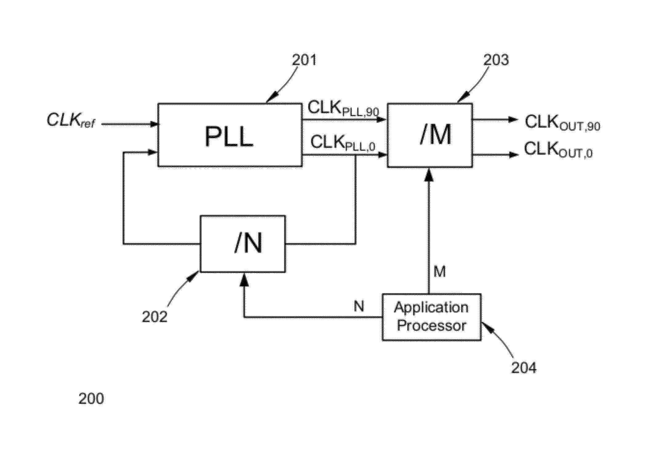
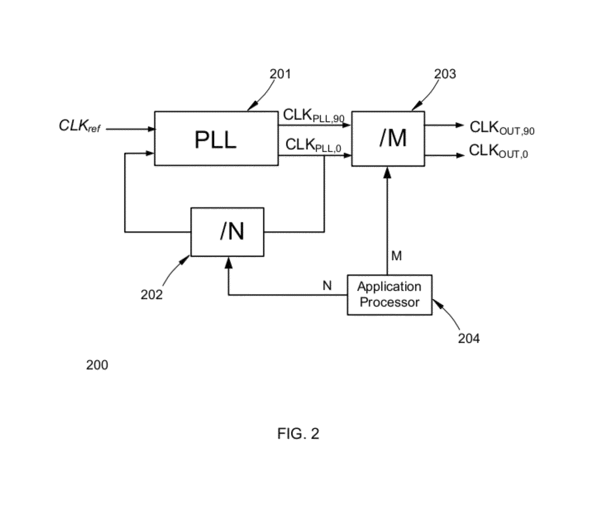
[0009]Various embodiments of the present invention relate to systems, devices and methods of frequency synthesis that generate in-phase and quadrature-phase clock signals at a programmable output frequency. This programmable frequency synthesizer avoids all issues caused by low reference frequencies and is capable of generating a wide range of frequencies while keeping the system design efficient and cost effective.
[0010]Certain embodiments of the frequency synthesizer include an application processor, a phase-locked loop circuit followed by a digital frequency divider. The application processor defines a ratio the clock frequency is programmed to relative to the reference frequency. The programmable frequency synthesizer uses a post-scaler instead of a prescaler. In various embodiments, the phase-locked loop may receive the input reference clock directly, and only need to be optimized at the specific input frequency. However, one skilled in the art will recognize that intermediate components may be located between the input reference clock and the phase-locked loop. The frequency from the input reference is relatively high, making the PLL easy to implement. The post-scaler is a digital frequency divider further dividing the PLL output by the ratio sent from the application processor. To avoid frequency doubling and excessive power consumption, the post-scaler employs two sub-dividing stages. The first divider stage includes a duty cycle equalizer circuit to ensure a 50% duty cycle clock output so that the second divide-by-two stage may conveniently generate both in-phase and quadrature-phase clock signals.

Problems solved by technology

At a low reference frequency, the performance and cost efficiency tends to be degraded for the phase-locked loop.
However, at a low operating frequency, the small charge-pump current increases the implementation difficulty.
In addition, with a low cutoff frequency, the frequency synthesizer requires a long time to settle; for example, for a loop bandwidth of 5 kHz, the settling time may last 200 μsec.
Therefore, frequency synthesizers functioning at low frequencies are undesirable due to performance and cost efficiency degradation of the phase-locked loop.
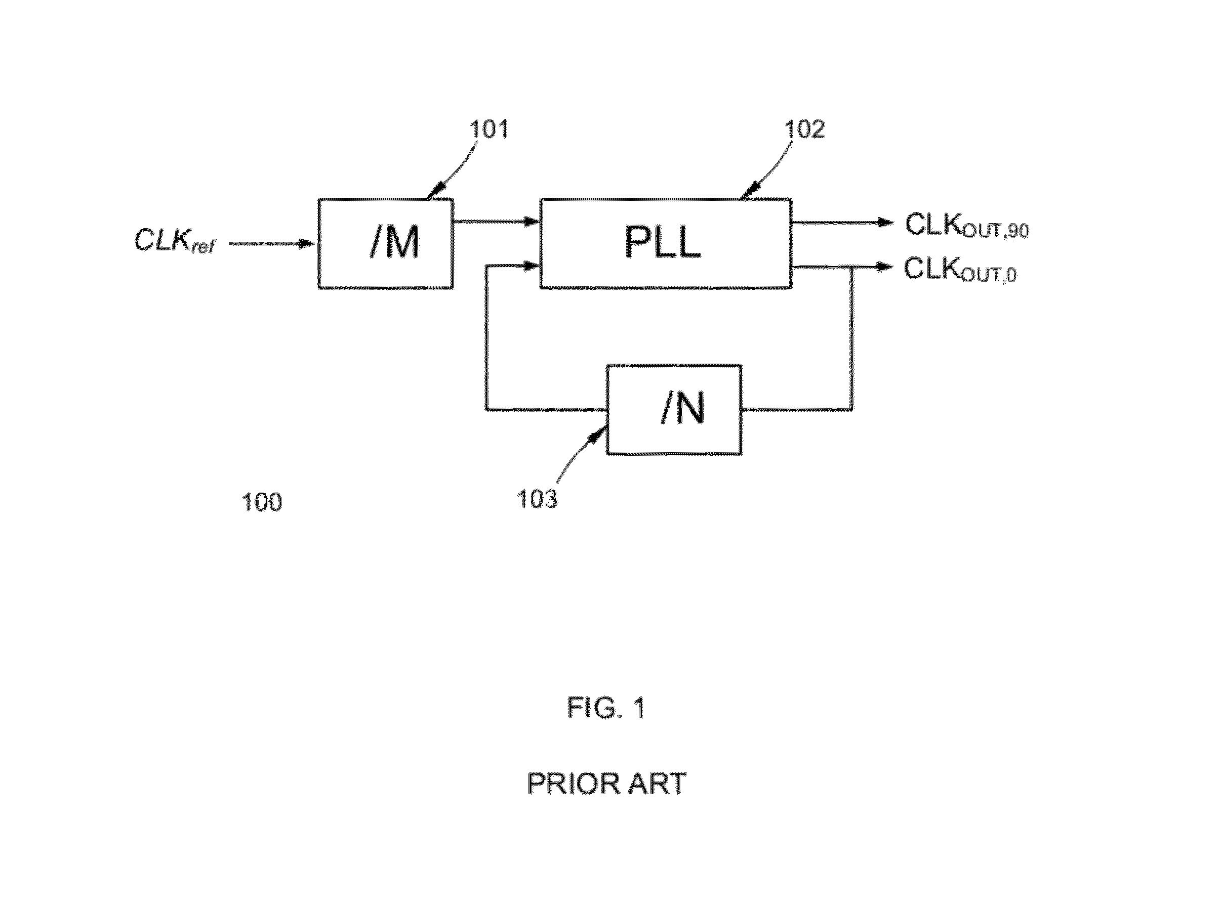
This approach not only increases design complexity but also introduces undesirable jitter and spurious sidebands.
However, doubling the frequency increases design complexity, power consumption, and may inject high-frequency glitches to the output signals.
Programmability and I / Q outputs present challenges for clock generation, especially for high-performance, low-cost and easy-to-implement solutions.

Method used


Image

  • Programmable frequency synthesizer with I/Q outputs
  • Programmable frequency synthesizer with I/Q outputs
  • Programmable frequency synthesizer with I/Q outputs

Examples


Embodiment Construction

[0021]Embodiments of the present invention provide systems, devices and methods for frequency synthesis. In the following description, for purposes of explanation, specific details are set forth in order to provide an understanding of the invention. It will be apparent, however, to one skilled in the art that the invention can be practiced without these details. One skilled in the art will recognize that embodiments of the present invention, described below, may be performed in a variety of ways and using a variety of structures. Those skilled in the art will also recognize additional modifications, applications, and embodiments are within the scope thereof, as are additional fields in which the invention may provide utility. Accordingly, the embodiments described below are illustrative of specific embodiments of the invention and are meant to avoid obscuring the invention.

[0022]Reference in the specification to “one embodiment” or “an embodiment” means that a particular feature, st...


PUM


Abstract

Various embodiments of the present invention relate to systems, devices and method of frequency synthesis that generate in-phase and quadrature-phase clock signals at a programmable frequency. The generated frequency, which can range from a fraction to multiples of the input reference frequency, is generated by dividers following a phase-locked loop, thus avoiding the use of a low input reference frequency as well as frequency doubling.

Description

BACKGROUND[0001]A. Technical Field[0002]The present invention relates to the field of electronics and data communications, and more particularly, to a programmable frequency synthesizer that generates both in-phase and quadrature-phase clock signals over a wide bandwidth.[0003]B. Background of the Invention[0004]Frequency synthesizers are electronic components for generating specific frequencies in reference to a fixed frequency provided by an external reference oscillator, and they are widely applied in modern communication systems, including radio receivers, mobile telephones, GPS systems and satellite receivers. The reference oscillator is normally a crystal oscillator that includes a vibrating crystal of piezoelectric material, so the reference frequency is maintained precise and stable. The core of a frequency synthesizer typically comprises a phase-locked loop (PLL) that aligns the phase and frequency of the output signal with the input reference. To obtain a fractional divisi...

Claims


Application Information

Patent Timeline
Patent Type & Authority Patents(United States)
IPC IPC(8): H03L7/06
CPCH04L27/01H03L7/183
Inventor CHU, MIN
Owner MAXIM INTEGRATED PROD INC
Why Eureka
Try Eureka