Imaging apparatus and imaging method

Active Publication Date: 2011-03-24
CANON KK
View PDF9 Cites 21 Cited by
  • Summary
  • Abstract
  • Description
  • Claims
  • Application Information

AI Technical Summary

Benefits of technology

[0006]The present invention is directed to a technique of preventing a closed-eye

Problems solved by technology

However, the imaging apparatus discussed in Japanese Patent Application Laid-Open No. 2006-163496 does not have a measure to t

Method used


Image

  • Imaging apparatus and imaging method
  • Imaging apparatus and imaging method
  • Imaging apparatus and imaging method

Examples


Embodiment Construction

[0016]Various exemplary embodiments, features, and aspects of the invention will be described in detail below with reference to the drawings.

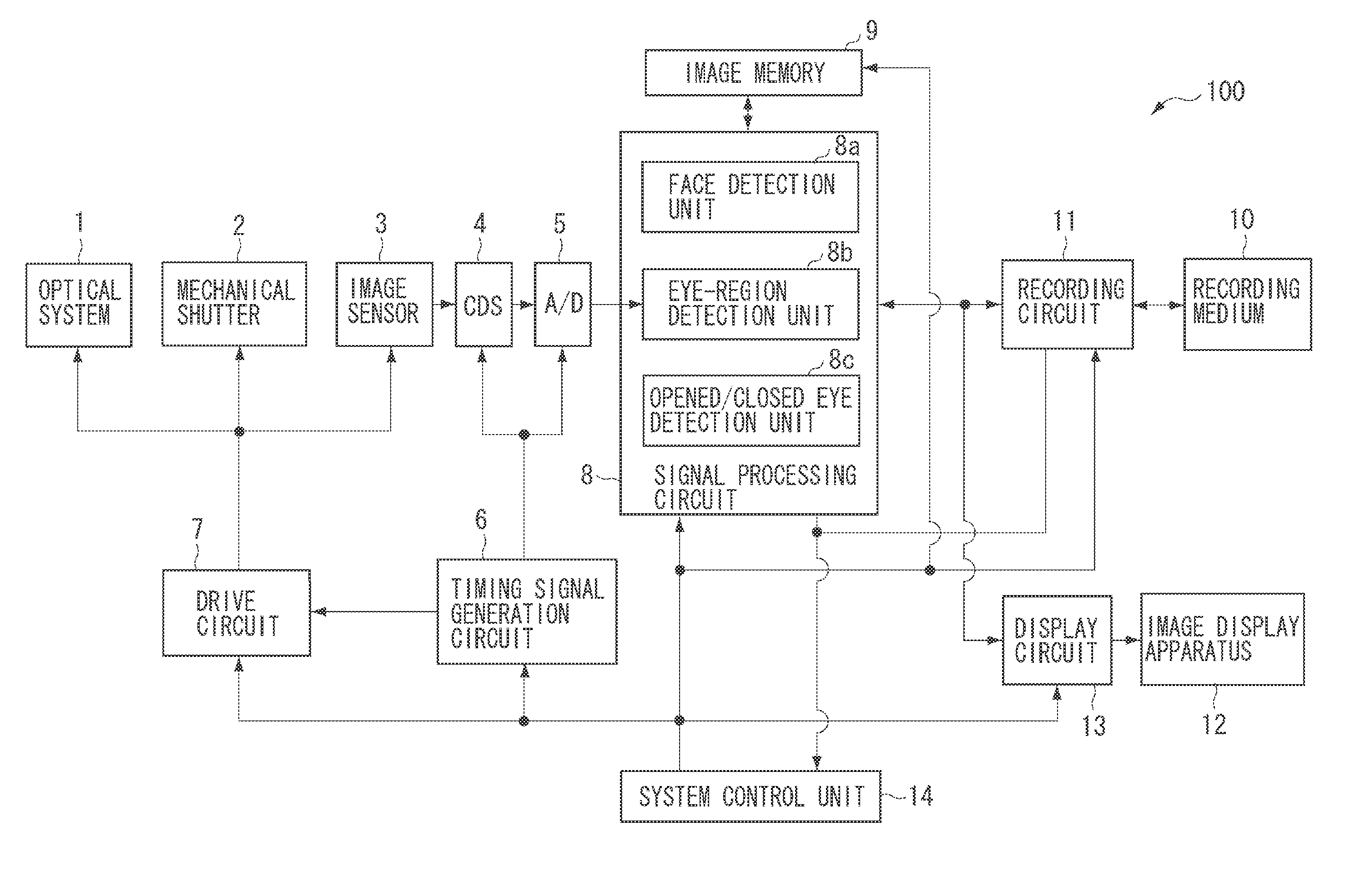
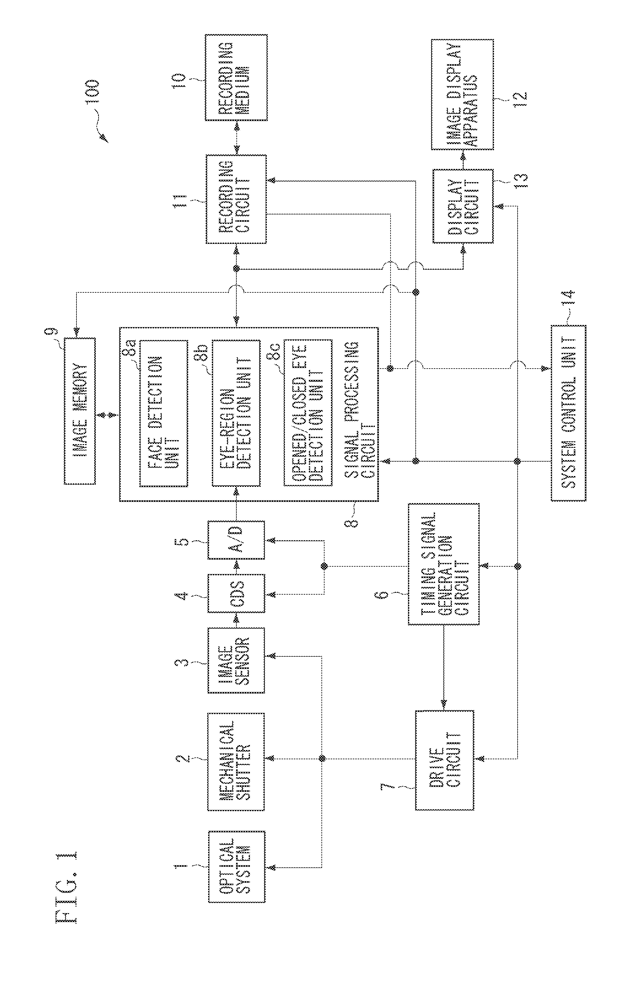
[0017]FIG. 1 is a block diagram illustrating a configuration of an imaging apparatus 100 according to an exemplary embodiment of the present invention.

[0018]In FIG. 1, an object image passing through an optical system 1 including a lens and a diaphragm is converted into an electric signal by an image sensor 3 including a photoelectric conversion element such as a charge-coupled device (CCD) or a complementary metal-oxide semiconductor (CMOS) sensor. A mechanical shutter 2 can block an object image from reaching the image sensor 3. A correlated double sampling (CDS) circuit 4 performs analog signal processing on image data generated by the image sensor 3, and an analog / digital (A / D) converter 5 converts an analog signal output from the CDS circuit 4 into a digital signal. A timing signal generation circuit 6 generates signals to control the imag...


PUM


Abstract

An imaging apparatus includes an imaging unit, a closed-eye detection unit configured to detect a face from an image captured by the imaging unit and to detect whether the detected face has closed eyes, and a control unit configured to determine whether to issue a warning about a captured image to be recorded according to a detection result detected by the closed-eye detection unit for the captured image to be recorded and a detection result detected by the closed-eye detection unit for a preview image captured before the image to be recorded is captured.

Description

BACKGROUND OF THE INVENTION[0001]1. Field of the Invention[0002]The present invention relates to an imaging apparatus and an imaging method, and more particularly to a technique well adaptable to prevent an erroneous determination in which a person having narrow eyes is determined to have closed eyes, even if he / she opens his / her eyes.[0003]2. Description of the Related Art[0004]Japanese Patent Application Laid-Open No. 2006-163496 discusses an imaging apparatus that can record images while identifying an image having a person closing his / her eyes and an image in which there is no one closing his / her eyes. The imaging apparatus described above records an image in which there is no one closing his / her eyes as a successful image, while recording an image having a person closing his / her eyes as a failed image.[0005]However, the imaging apparatus discussed in Japanese Patent Application Laid-Open No. 2006-163496 does not have a measure to the case in which a person having narrow eyes is...

Claims


Application Information

Patent Timeline
IPC IPC(8): H04N5/228G06K9/46
CPCH04N5/23219H04N5/907H04N5/772H04N5/23222H04N23/64H04N23/611
Inventor OKADA, MASAO
Owner CANON KK
Why Eureka
Try Eureka