

Fuel tank
a technology for fuel tanks and tanks, applied in the field of fuel tanks, can solve problems such as the reduction of the effectiveness of the liquid seal, and achieve the effect of reducing the flow through the fuel vapor filter
- Summary
- Abstract
- Description
- Claims
- Application Information
AI Technical Summary
Benefits of technology
Problems solved by technology
Method used
Image


Examples
Embodiment Construction
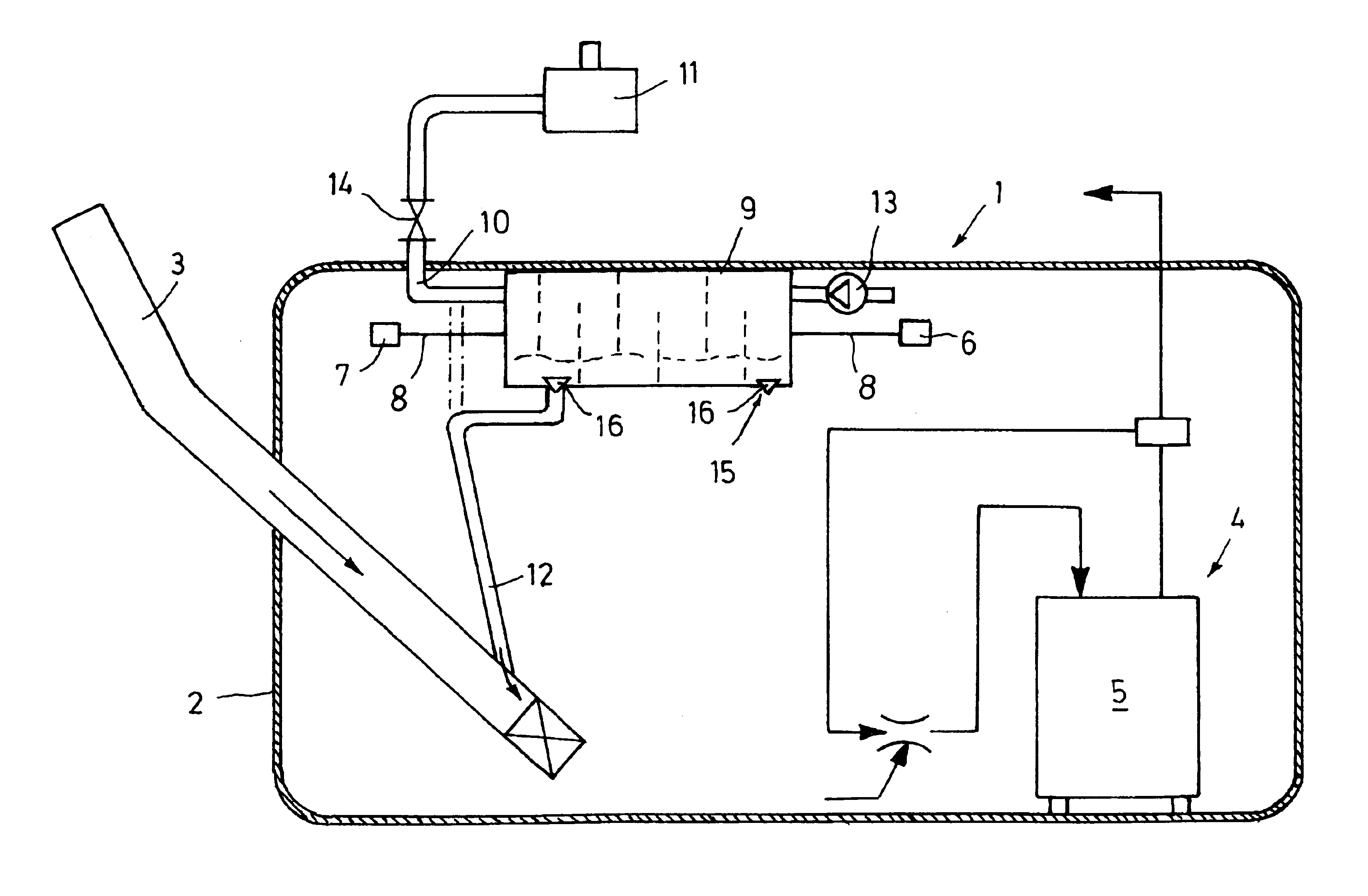
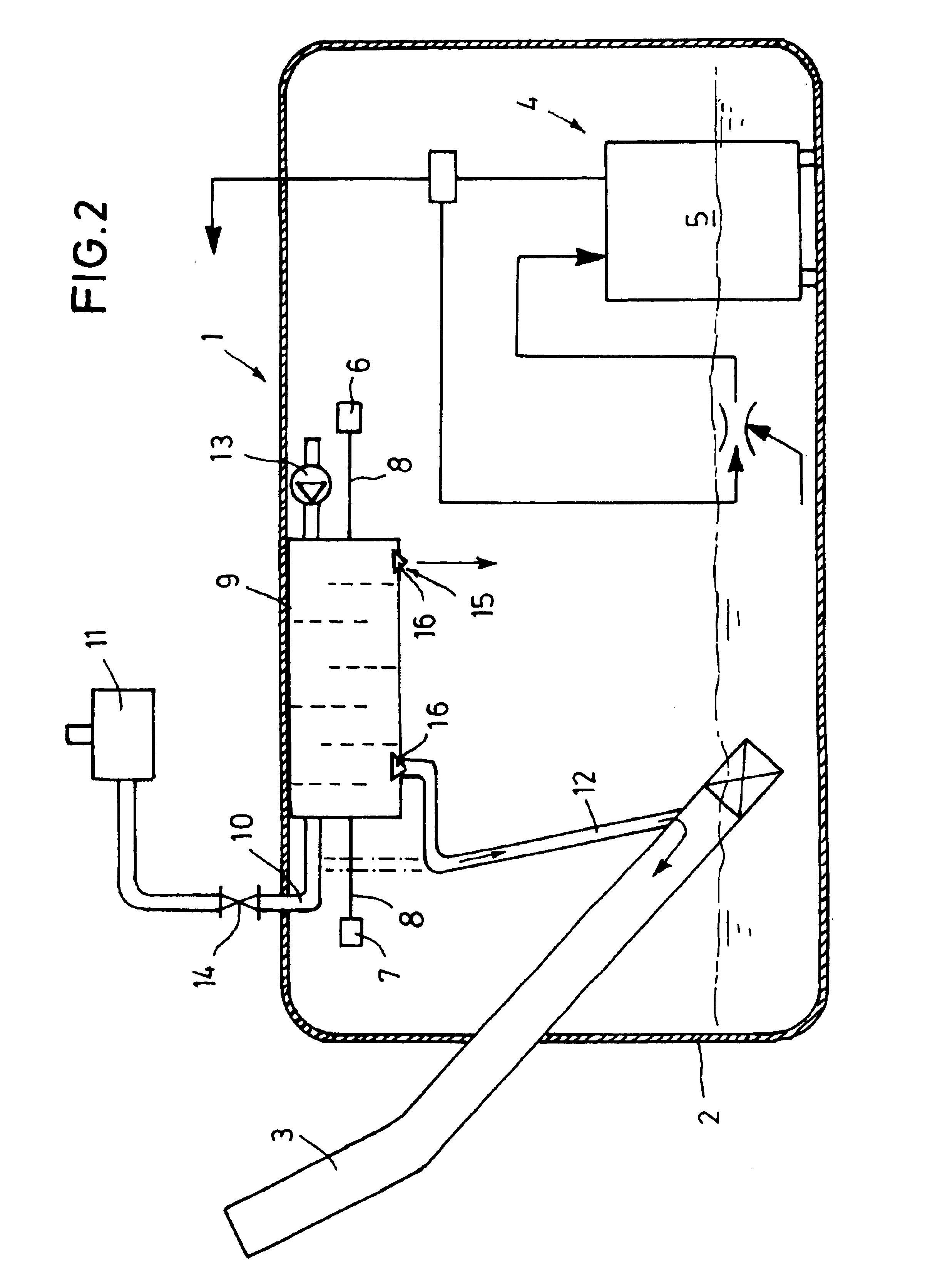
[0023]Referring firstly to FIG. 1, reference numeral 1 therein denotes a fuel tank, for example for a motor vehicle, which is in the form of an extrusion blow-molded fuel tank. Reference numeral 2 in FIG. 1 denotes the wall of the tank 1, which is very substantially non-transmissive in relation to fluid hydrocarbons to prevent the permeation thereof. It will be appreciated that the structure and mode of manufacture of the fuel tank 1 is not relevant to the present invention as the fuel tank 1 can equally be made from sheet metal or in a multi-part structure from plastic material, for example it can comprise injection-molded casing portions which are assembled together.
[0024]The fuel tank 1 includes a filler pipe 3 and a fuel delivery unit 4 disposed in the internal volume of the fuel tank 1. The fuel delivery unit 4 comprises a swirl or surge pot 5 as a reservoir for a fuel delivery pump (not shown) which is arranged therein, to ensure that the pump has a steady supply of fuel. For ...
PUM
| Property | Measurement | Unit |
|---|---|---|
| Volume | aaaaa | aaaaa |
| Level | aaaaa | aaaaa |
Abstract
Description
Claims
Application Information