
Camera control apparatus, camera system, electronic conference system, and camera control method

a control apparatus and camera technology, applied in the field of camera control apparatus, can solve the problems of troublesome operation and large burden on the operator, and achieve the effect of reliably photographing one person, simple operation and reliable photographing one person

Inactive Publication Date: 2010-03-09
SONY CORP
View PDF6 Cites 24 Cited by
  • Summary
  • Abstract
  • Description
  • Claims
  • Application Information

AI Technical Summary

Benefits of technology

The present invention provides a camera control apparatus and method for automatically photographing one person among a plurality of persons by using a camera without the need for an operator to manually adjust the camera's direction. The apparatus includes a storage section that stores face direction information for each person to be photographed, a face position detection section that detects the position of a person's face in a photographed image signal, and a registration section that computes and stores the face direction information based on the detection result and the camera's current photographing direction. The driving control section reads the face direction information and controls the camera's driving apparatus to change the photographing direction so that the person's face is positioned in the center of the screen. This invention simplifies the process of photographing multiple people and reduces the burden on the operator.

Problems solved by technology

However, in an operation technique for gradually changing the photographing direction and a zoom magnification ratio of the camera, there is the problem in that, for quickly moving the photographing direction and reliably projecting a speaking person in the central portion of the screen, the burden on the operator is large.
However, for that purpose, it is necessary to prestore the position of the speaker before the system is used, and the operation is troublesome.

Method used


Image

  • Camera control apparatus, camera system, electronic conference system, and camera control method
  • Camera control apparatus, camera system, electronic conference system, and camera control method
  • Camera control apparatus, camera system, electronic conference system, and camera control method

Examples


first embodiment

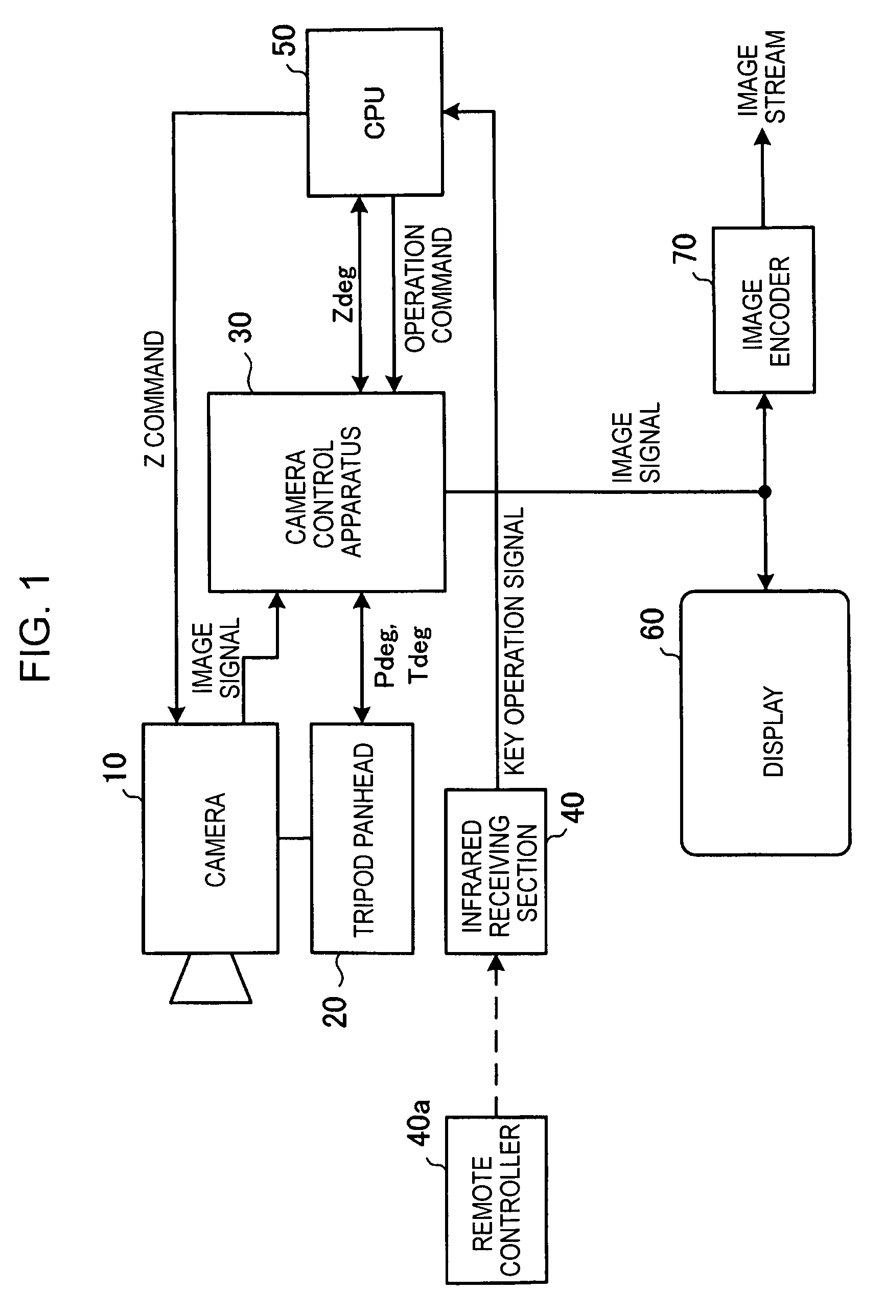
[0026]FIG. 1 shows a system configuration of a camera system according to a first embodiment of the present invention.

[0027]The camera system shown in FIG. 1 is designed to photograph a plurality of persons attending a conference by using one camera 10. This system includes a camera 10 having a zoom function, a tripod panhead 20 for changing the photographing direction of the camera 10, a camera control apparatus 30 for controlling the operation of the tripod panhead 20, an infrared receiving section 40 for receiving an infrared signal from a remote controller 40a, a CPU 50 for centrally controlling the overall system, a display 60 for displaying a photographed image, etc., and an image encoder 70 for compressing and coding an image signal.

[0028]In the camera 10, the photographing direction thereof is changed in a horizontal or vertical direction by the tripod panhead 20, and the focal length of a zoom lens is controlled in accordance with a control signal (zoom command) from the CP...

second embodiment

[0095]FIG. 8 shows a system configuration of a camera system according to a second embodiment of the present invention. Functions in FIG. 8 corresponding to those in FIG. 1 are designated with the same reference numerals, and accordingly, descriptions thereof are omitted.

[0096]The camera system shown in FIG. 8 includes, in addition to the configuration of the system shown in FIG. 1, a voice signal analysis apparatus 80, and two microphones 81 and 82. The microphones 81 and 82 collect voices of the participants in a conference room in which photographing is being performed by the camera 10, and the collected voice signal is input to the voice signal analysis apparatus 80. The voice signal analysis apparatus 80 extracts human voices from the two input audio signals, estimates the direction in which the voice is produced, and outputs voice direction information indicating the direction to the camera control apparatus 30. As a result, the camera control apparatus 30 specifies the direct...


PUM


Abstract

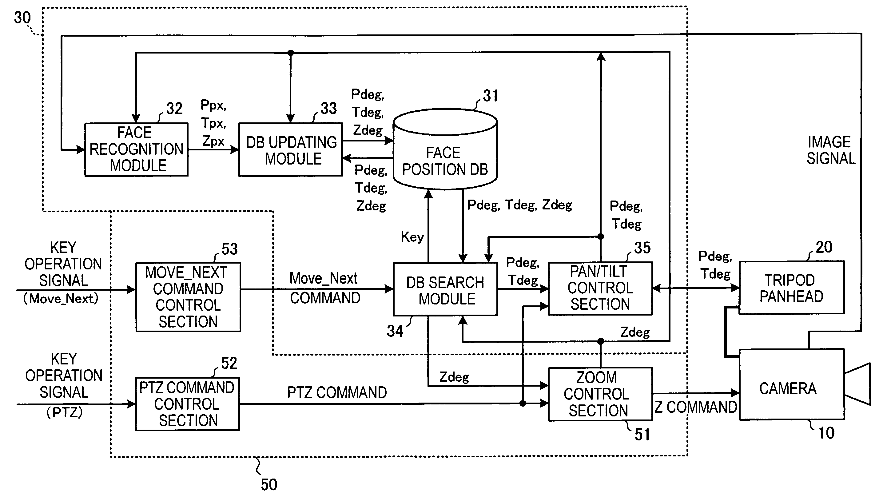
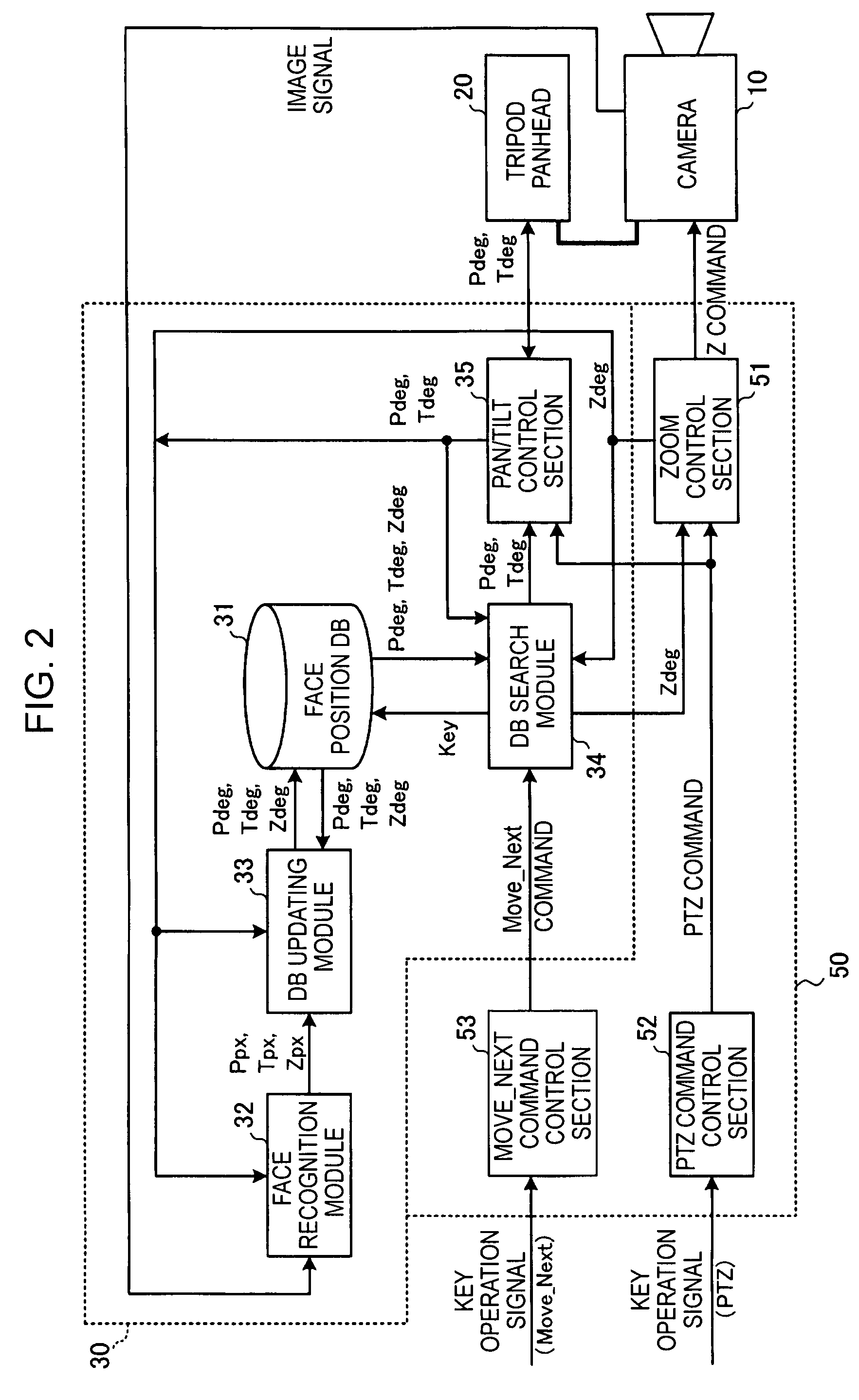
A camera control apparatus includes a storage section storing, for each person to be photographed, face direction information when each face of a plurality of persons to be photographed by a camera is positioned in the central portion of a photographing range by the camera; a face position detection section detecting a position of a face of a person from a photographed image signal of the camera; a registration section computing face direction information on the basis of a detection result by the face position detection section and information indicating a current photographing direction of the camera and registering the face direction information in the storage section; and a driving control section reading face direction information corresponding to a person specified by an operation input from a user and controlling the driving apparatus in accordance with the face direction information in order to change the photographing direction of the camera.

Description

CROSS REFERENCES TO RELATED APPLICATIONS[0001]The present invention contains subject matter related to Japanese Patent Application JP 2005-009417 filed in the Japanese Patent Office on Jan. 17, 2005, the entire contents of which are incorporated herein by reference.BACKGROUND OF THE INVENTION[0002]1. Field of the Invention[0003]The present invention relates to a camera control apparatus for controlling a photographing range of a camera including a driving apparatus for changing a photographing direction, to a camera system and an electronic conference system including the camera control apparatus, and to a camera control method. More particularly, the present invention relates to a camera control apparatus having improved convenience of an operation for changing a photographing direction of a camera, a camera system, an electronic conference system, and a camera control method.[0004]2. Description of the Related Art[0005]In recent years, a television conference system capable of hol...

Claims


Application Information

Patent Timeline
Patent Type & Authority Patents(United States)
IPC IPC(8): H04N7/15H04N23/40
CPCH04N5/232H04N7/147H04N7/142H04N23/61H04N23/695E02D29/0241E02D2300/0085
Inventor MATSUI, TAKESHI
Owner SONY CORP
Learn More