Tactical foregrip assembly

a foregrip and tactical technology, applied in the direction of butts, firing/trigger mechanisms, weapons, etc., can solve the problems of life-threatening situations, operator is vulnerable to receiving fire, and unnecessary exposure to the operator, so as to improve the position, visibility and time response, and maximize visibility

Active Publication Date: 2010-03-16
BREACHING TECH
View PDF13 Cites 115 Cited by
  • Summary
  • Abstract
  • Description
  • Claims
  • Application Information

AI Technical Summary

Benefits of technology

[0010]The present invention serves to improve the position, visibility and time response by allowing an operator to quickly place a light, laser, or other accessory to maximize visibility. The present invention also allows the operator to remain behind cover or low to the ground. In addition, the present invention allows a firearm operator to quickly switch between multiple rail-mounted accessories (e.g., switching between a close quarters battle sight and a high power scope) with or without rotating the foregrip assembly to a more favorable position.

Problems solved by technology

Such room clearing operations, however, can be and often are life threatening situations in which an operator is vulnerable to receiving fire.
Typical foregrip and accessory mounting systems do not allow the operator to rotate the grip or light so that the operator may optimize his or her position behind cover.
When mounted on a bottom rail, the weapon sling can often interfere with the projected light, which would require the operator to divert his or her attention from a threat or threat area to repositioning the sling.
When mounted on a side rail, the orientation of the light causes unnecessary exposure to the operator when circumventing corners.
If the operator desires to align an eye with the firearm sight, this results in increased exposure to the operator, who must rollout the firearm as well as his or her body around the turn further than in a well-lighted area.
The same problem occurs when if the light is mounted on a right side rail and a right turn must be negotiated.
This, however, alters the flight path of the bullet as it would be fired from an upright firing position.

Method used


Image

  • Tactical foregrip assembly
  • Tactical foregrip assembly
  • Tactical foregrip assembly

Examples


Embodiment Construction

[0025]The present invention is a tactical foregrip assembly intended for use with, and longitudinally aligned on, the receiver of a firearm. As used herein, “proximal” means proximal to the muzzle of the firearm when the present invention is installed thereon, while “distal” means distal to the muzzle end of the firearm when the present invention is installed thereon.

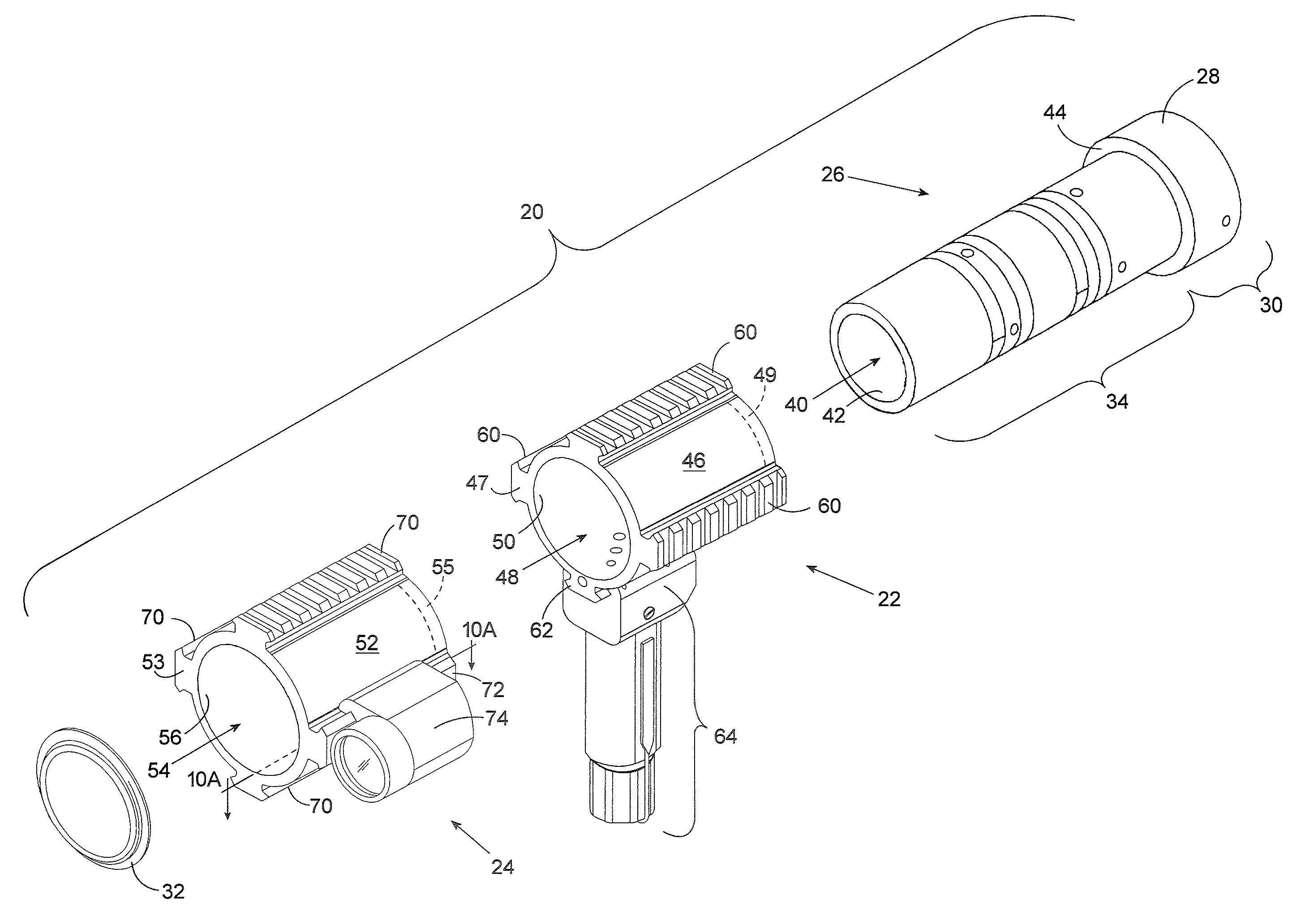
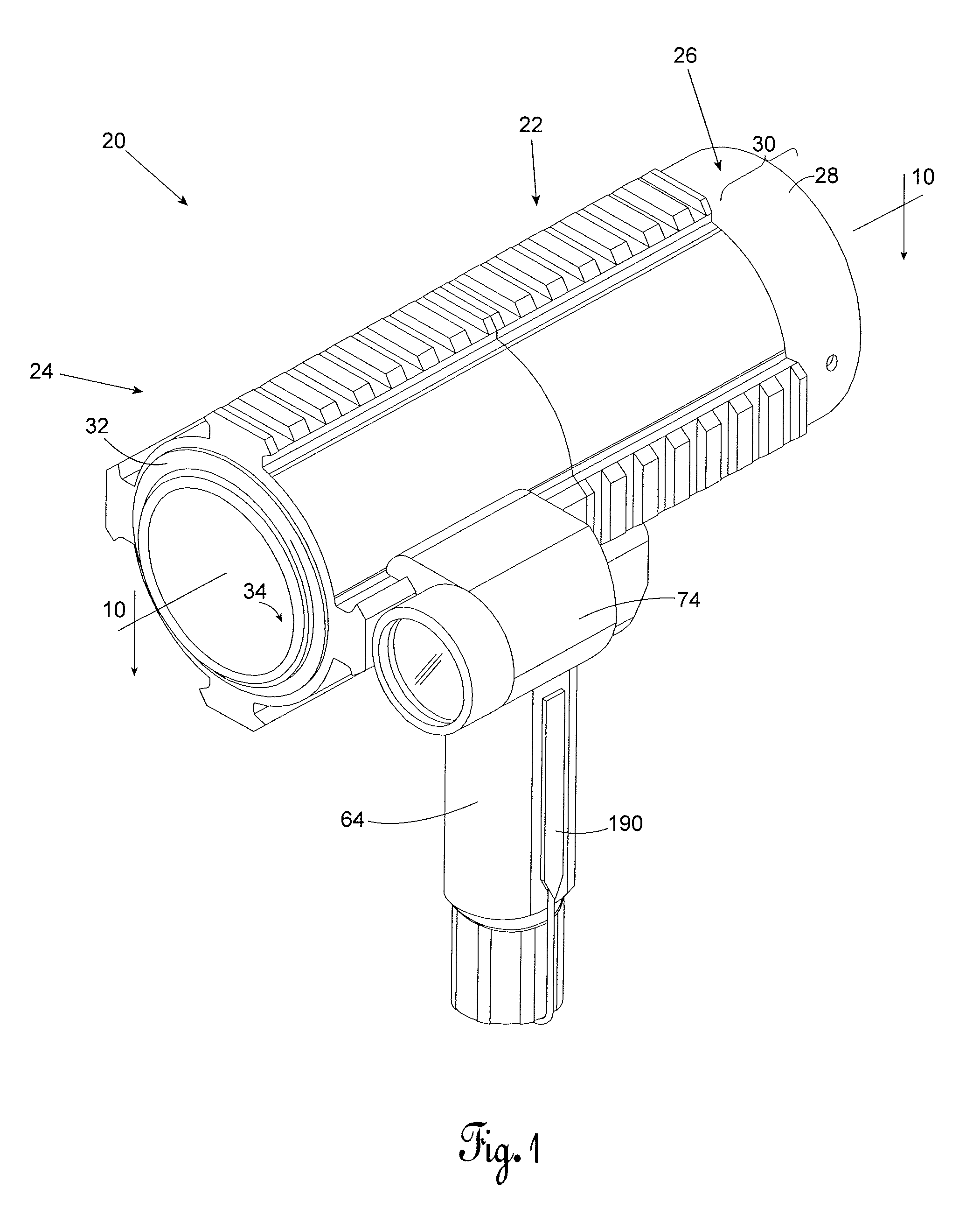
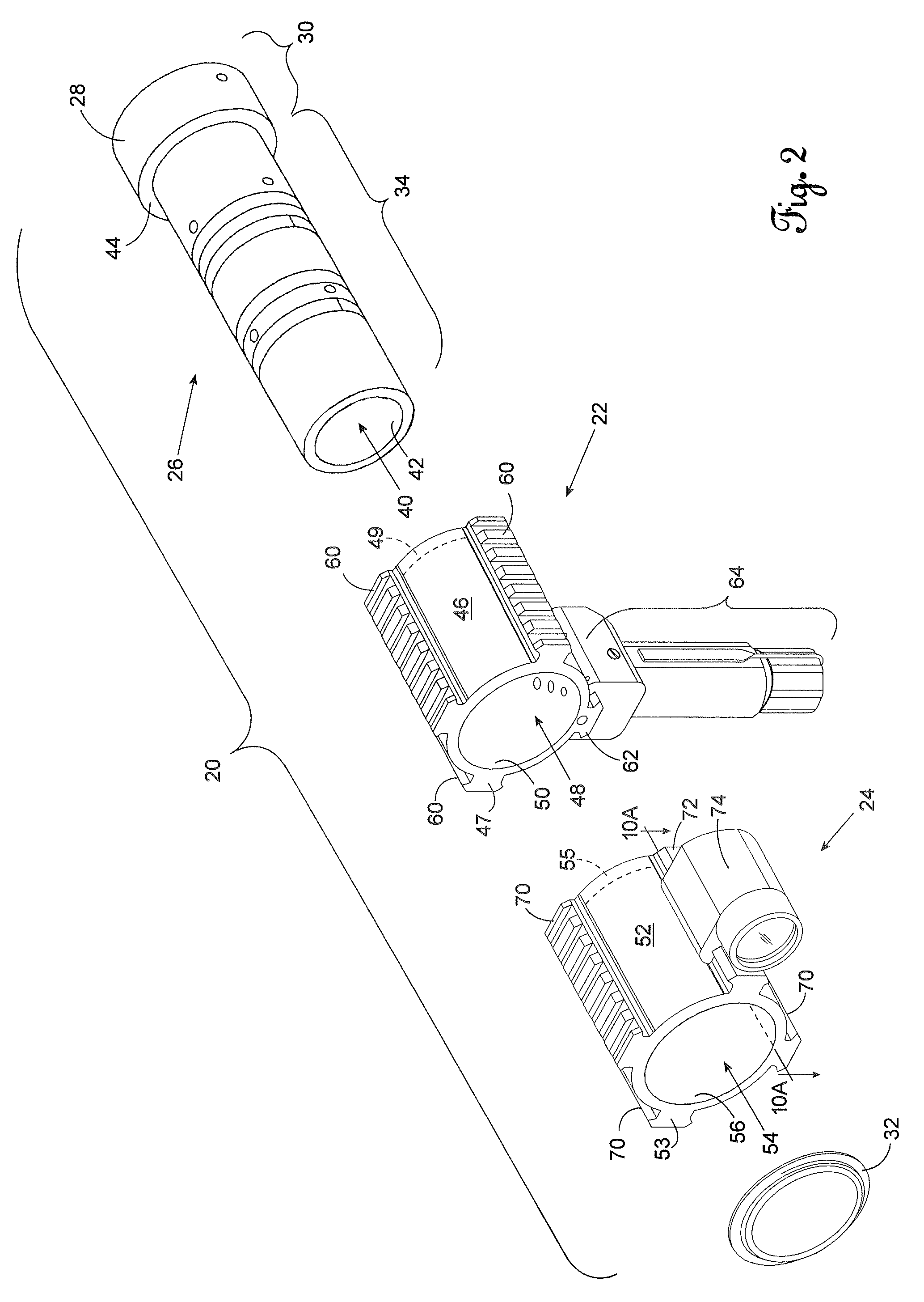
[0026]FIG. 1 illustrates the preferred embodiment of the tactical foregrip assembly 20. A grip mount assembly 22 and a light mount assembly 24 are positioned about a stationary mount assembly 26 that is attachable to the receiver of a firearm. The stationary mount assembly 26 includes a nylon (30% glass filled) barrel mount 28 with a distal second portion 30 as well as a proximal first portion 34 about which the grip mount assembly 22 and light mount assembly 24 are positioned. A spring clip 32 fixed about the first portion 34 of the barrel mount 28 prevents movement of the grip mount assembly 22 and light mount assembl...


PUM


Abstract

A tactical foregrip assembly for use with a firearm, the assembly having an independently rotatable grip mount assembly and an independently rotatable light mount assembly. The invention comprises a stationary mount assembly attachable to the receiver of a firearm, a grip mount assembly radially rotatable about and electrically coupled to the stationary mount assembly, and a light mount assembly radially rotatable about and electrically coupled to the stationary mount and engagable with said grip assembly. The present invention allows the operator to provide light to illuminate an area while simultaneously positioning himself in a manner so as to maximally use available cover.

Description

CROSS REFERENCE TO RELATED APPLICATIONS[0001]This original nonprovisional application claims the benefit of U.S. provisional application No. 60 / 956,264, filed Aug. 16, 2007 and entitled “Tactical Fore-End Assembly,” which is incorporated by reference herein.STATEMENT REGARDING FEDERALLY SPONSORED RESEARCH OR DEVELOPMENT[0002]Not applicable.BACKGROUND OF THE INVENTION[0003]1. Field of the Invention[0004]The present invention relates to an accessory mounting platform for firearms. More specifically, the invention is a tactical foregrip assembly that provides a dynamically positionable foregrip in combination with an independently-positionable light assembly.[0005]2. Description of the Related Art[0006]Public safety and military personnel are often faced with the need to safely arrest and remove persons from structures that contain multiple rooms. Such room clearing operations, however, can be and often are life threatening situations in which an operator is vulnerable to receiving fir...

Claims


Application Information

Patent Timeline
Patent Type & Authority Patents(United States)
IPC IPC(8): F41G1/35
CPCF41C23/14F41C27/00F41G11/003F41C23/16
Inventor PHILLIPS, DARRONFERRIS, MARK M.GONTHIER, ARTHUR F.
Owner BREACHING TECH
Why Eureka
Try Eureka