Mounting system for muzzle devices and firearms

a technology for mounting systems and muzzle devices, which is applied in the field of mounting systems for muzzle devices and firearms, can solve the problems of inability to accurately adjust the shooting angle, inability to mount and dismount, and inability to meet the needs of shooting accuracy, etc., and achieve the effect of quick and easy removal of the muzzle device from the firearm

Active Publication Date: 2010-03-16
SMITH & WESSON
View PDF41 Cites 47 Cited by
  • Summary
  • Abstract
  • Description
  • Claims
  • Application Information

AI Technical Summary

Benefits of technology

[0003]Is often desirable to mount removable devices at the muzzle of a firearm. A sound suppressor or silencer reduces the sound of the discharge of a firearm; a muzzle brake or compensator reduces recoil forces; a blank firing adapter is useful for training and for launching of grenades and rescue devices.
[0007]Another approach has been to design the mounting system to allow mounting to the existing flash hider on the standard rifle, and U.S. Pat. No. 5,773,746 (Vaden) is an example of this approach. This patent discloses a mounting system that allows for the quick attachment and detachment of a sound suppressor to the M4 / M16A2 series of rifles that are equipped with a standard flash hider or compensator. The Vaden patent features the use of 3 pivoting fingers that are moved into position and locked onto the rear of the flash hider via the use of a rotating collar. A combination of left and right hand threads in the rotating collar and body of the mount meant that the collar was simply and quickly rotated one way to lock and the other way to unlock the sound suppressor from the flash hider.
[0012]It is therefore an object of this invention to provide a mounting system that provides a quick, secure and mechanically strong mounting system for muzzle devices such as sound suppressors, muzzle brakes, recoil compensators and BFAs (Blank Firing Adapters) to a firearm, that secures the muzzle device to the firearm regardless of vibrations from firing of the rifle, and allows for the quick and easy removal of the muzzle device from the firearm.
[0013]The present invention overcomes the limitations of the prior art by providing a system for connecting an accessory to a firearm having an enlarged muzzle portion has a body with a bore sized to closely receive the enlarged portion. The body has a stop to limit the insertion depth of the muzzle. A gate is received by the body for movement along the path perpendicular to the bore axis. The gate has a recessed area sized to receive the enlarged muzzle portion. A spring generates axial force to retain the muzzle portion within the recessed area. Compression of the spring enables movement of the gate to shift between an open and closed position, so that the accessory may be removed or installed when in the open position, and secured when in the closed position.

Problems solved by technology

This has the disadvantage of being slow to mount and dismount, a serious concern in military and law enforcement contexts.
Other prior art mounts provide quicker disconnection, but suffer other disadvantages such as inadequate repeatable precision of alignment (which generates shooting inaccuracy), complexity and cost of manufacture, and durability.
However, there are a number of problems with prior art patents and existing practiced prior art.
These problems include unwanted modifications to the barrel, the undesirable requirement of a proprietary flash hider, and the associated costs and time due to the installation of a proprietary flash hider.
One of the major problems is that existing systems require modifications to the host firearm.
This adds an unwanted burden at the stage of designing the firearm, and requires that the firearm manufacturer be cognizant of a possible requirement to attach a sound suppressor to the firearm as part of the design criteria.
All of the above systems have significant disadvantages in terms of cost, reliability, durability, accuracy, and / or combinations of these.

Method used


Image

  • Mounting system for muzzle devices and firearms
  • Mounting system for muzzle devices and firearms
  • Mounting system for muzzle devices and firearms

Examples


Embodiment Construction

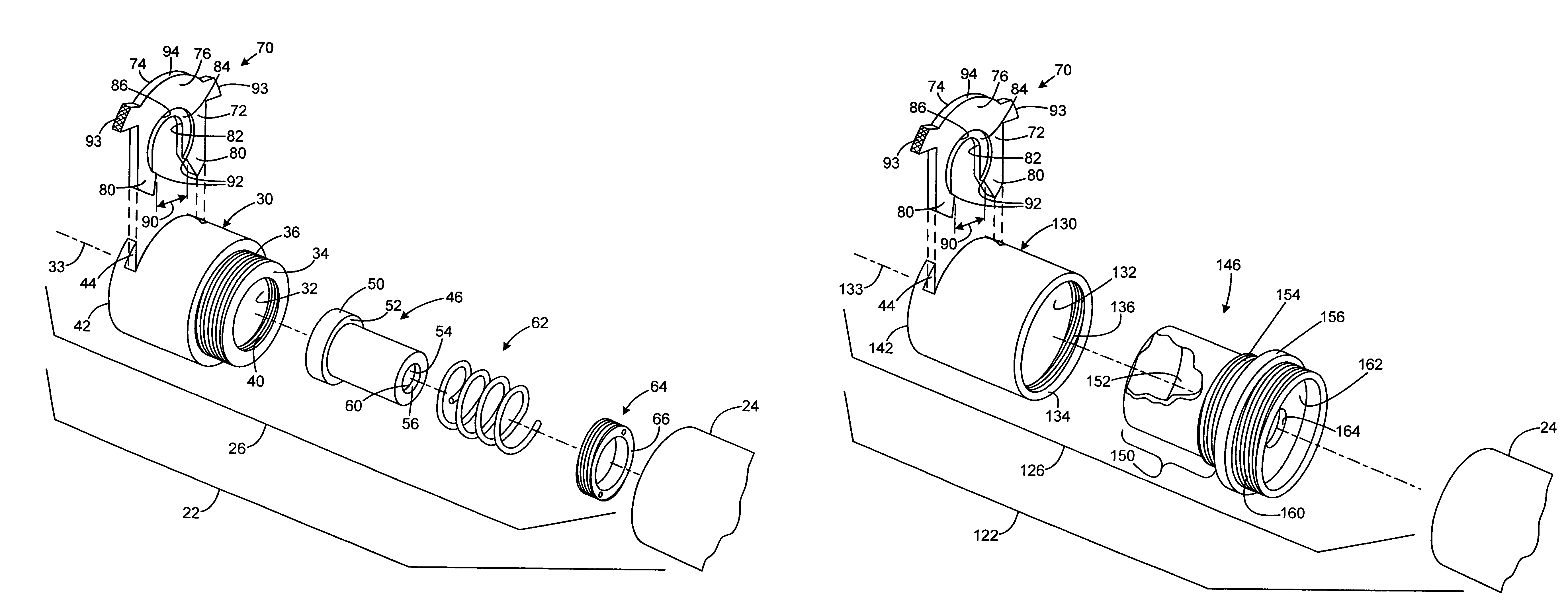
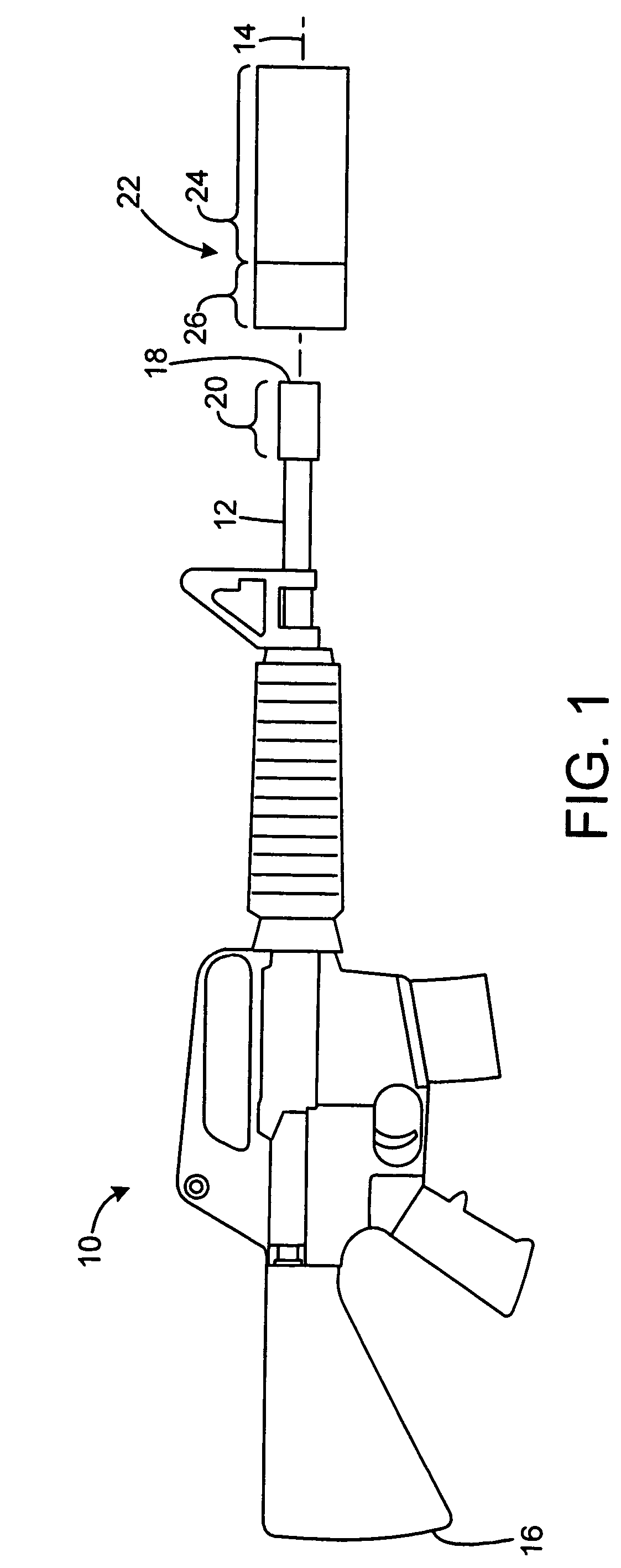
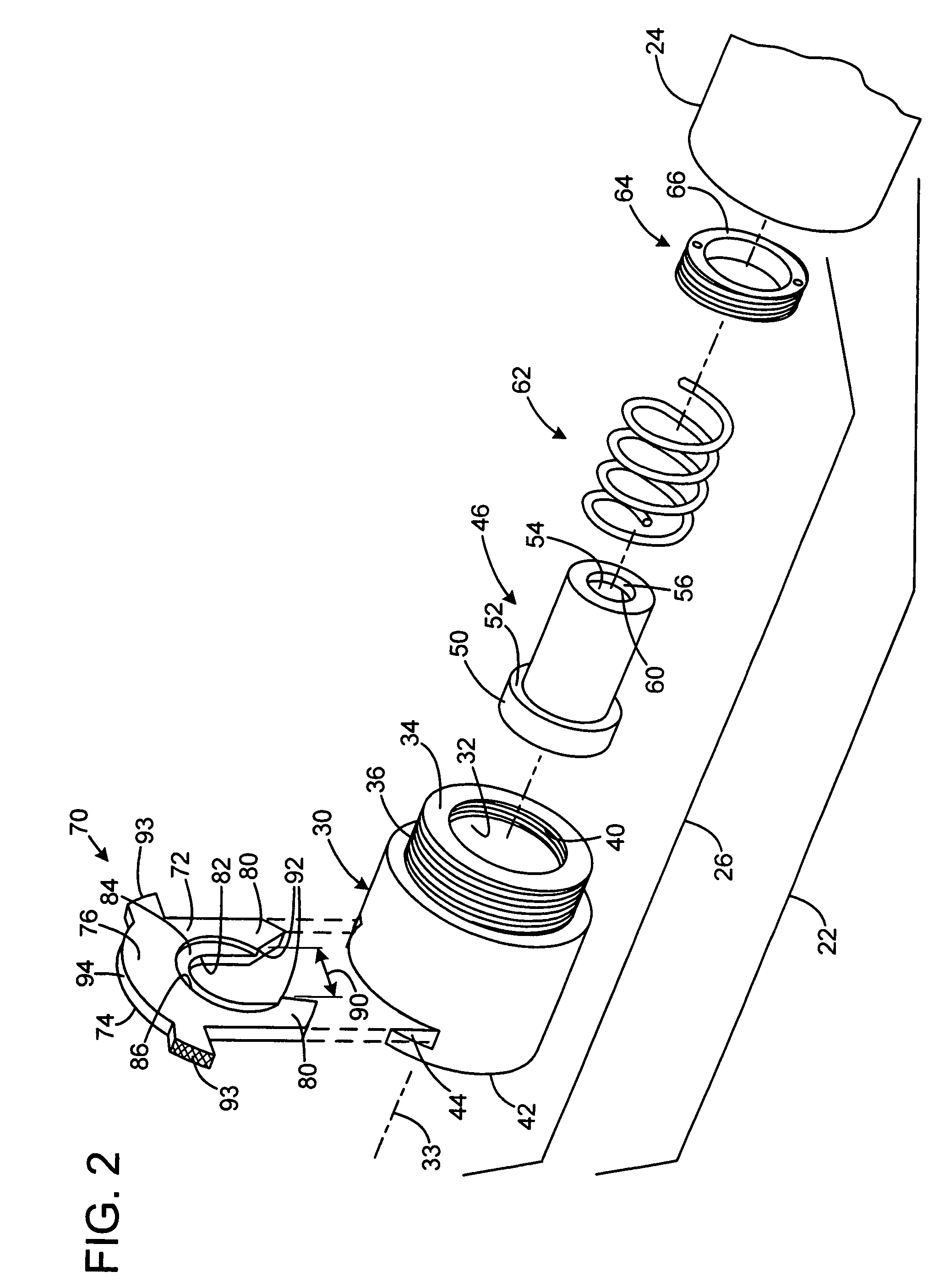
[0021]FIG. 1 shows a rifle 10 having a barrel 12 defining an axis 14. The rifle has a rear end 16, and the barrel has a forward muzzle end 18 having an enlarged end portion 20. The end portion 20 has a cylindrical shape with a diameter larger than that of the barrel 12. In one application for the preferred embodiment the barrel has an outside diameter of 0.735 inch just rearward of the end portion 20, and the enlarged portion 20 has a diameter of 0.860 inch, and a length of 1.75 inch. The end portion may be a permanently or temporarily mounted flash hider, muzzle brake, or other facility, or may be a dedicated integral or attached element specifically for receiving the attachment discussed below.

[0022]In the application illustrated in the preferred embodiment, a sound suppressor 22 is prepared for installation at the muzzle. The suppressor 22 has an elongated forward portion 24 having an expansion chamber and including baffles and other functional elements. A adapter or rear portion...


PUM


Abstract

A system for connecting an accessory to a firearm having an enlarged muzzle portion has a body with a bore sized to closely receive the enlarged portion. The body has a stop to limit the insertion depth of the muzzle. A gate is received by the body for movement along the path perpendicular to the bore axis. The gate has a recessed area sized to receive the enlarged muzzle portion. A spring generates axial force to retain the muzzle portion within the recessed area. Compression of the spring enables movement of the gate to shift between an open and closed position, so that the accessory may be removed or installed when in the open position, and secured when in the closed position.

Description

REFERENCE TO RELATED APPLICATION[0001]This non-provisional patent application is related to provisional application for patent application No. 60 / 731,002 filed Oct. 28, 2005.FIELD OF THE INVENTION[0002]The present invention relates to firearms, and more particularly to facilities for mounting on the muzzle a device, such as a sound suppressor, muzzle brake, recoil compensator or blank firing adapter.BACKGROUND AND SUMMARY OF THE INVENTION[0003]Is often desirable to mount removable devices at the muzzle of a firearm. A sound suppressor or silencer reduces the sound of the discharge of a firearm; a muzzle brake or compensator reduces recoil forces; a blank firing adapter is useful for training and for launching of grenades and rescue devices.[0004]A conventional muzzle mounted accessory may be internally threaded to engage a threaded and of a firearm barrel. This has the disadvantage of being slow to mount and dismount, a serious concern in military and law enforcement contexts. Other...

Claims


Application Information

Patent Timeline
Patent Type & Authority Patents(United States)
IPC IPC(8): F41A21/48
CPCF41A21/325
Inventor DATER, PHILIP H.HOEL, THOMAS T.
Owner SMITH & WESSON
Why Eureka
Try Eureka