
Chiller sound reduction control system and method

a control system and chiller technology, applied in the direction of cooling fluid circulation, domestic cooling apparatus, lighting and heating apparatus, etc., can solve the problems of high cost of modification or replacement, uncomfortable levels in interior building temperatures, etc., and achieve the effect of not completely sacrificed comfort cooling in interior space and selective reduction of sound generated by chiller system

Active Publication Date: 2010-06-29
JOHNSON CONTROLS TYCO IP HLDG LLP
View PDF46 Cites 27 Cited by
  • Summary
  • Abstract
  • Description
  • Claims
  • Application Information

AI Technical Summary

Benefits of technology

The present invention is about a method and system for reducing the sound generated by a chiller system. The method involves receiving a sound control signal at a control panel, measuring the operating speed of the compressor and the operating parameter of at least one condenser fan, and controllably altering the operating configuration of the at least one condenser fan and / or reducing the speed of the compressor to reduce the noise generated by the chiller system. The system includes a control panel, a compressor, a condenser arrangement, at least one condenser fan, and an evaporator arrangement. The invention allows for selective and periodic reduction of sound without requiring mechanical modifications to system components and maintaining comfort cooling in the interior space.

Problems solved by technology

However, disabling the chiller system means that no cooling can be performed by the chiller systems, thus causing the interior building temperatures to rise to uncomfortable levels.
However, such modifications or replacements can be expensive as a result of the materials, labor, and downtime costs that are potentially involved.

Method used


Image

  • Chiller sound reduction control system and method
  • Chiller sound reduction control system and method
  • Chiller sound reduction control system and method

Examples


Embodiment Construction

[0019]The present invention therefore provides systems and methods for selectively controlling the speed of the compressor and the condenser fans of a chiller system to reduce sound generated by the system at selected times. The selective operation of the condenser fans can include any combination of disabling one or more fans, operating less than all fans, operating one or more fans at lower fixed speed, operating one or more fans at a lower variable speed. It is noted that the control of fan speed, as it is describe below, also includes switching some or all of the condenser fans on or off.

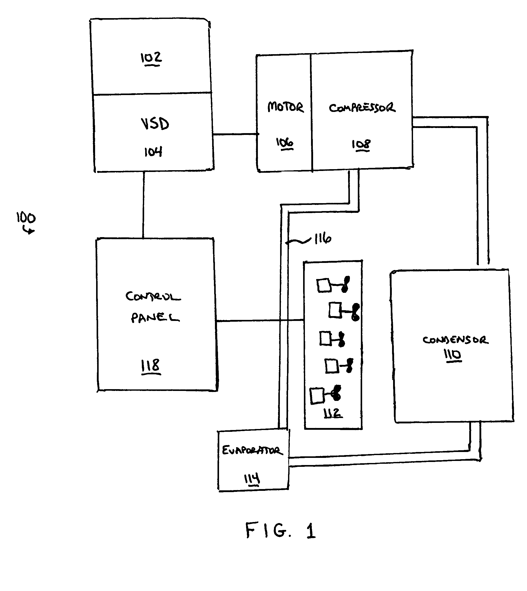
[0020]FIG. 1 illustrates generally a chiller, HVAC or refrigeration system 100 that can be used with the present invention. An AC power source 102 supplies a variable speed drive (VSD) 104, which powers one or more motors 106. Each motor 106 is used to drive a corresponding compressor 108 that feeds high-pressure and high-temperature refrigerant gas to a condenser 110. The compressor 108 is pref...


PUM


Abstract

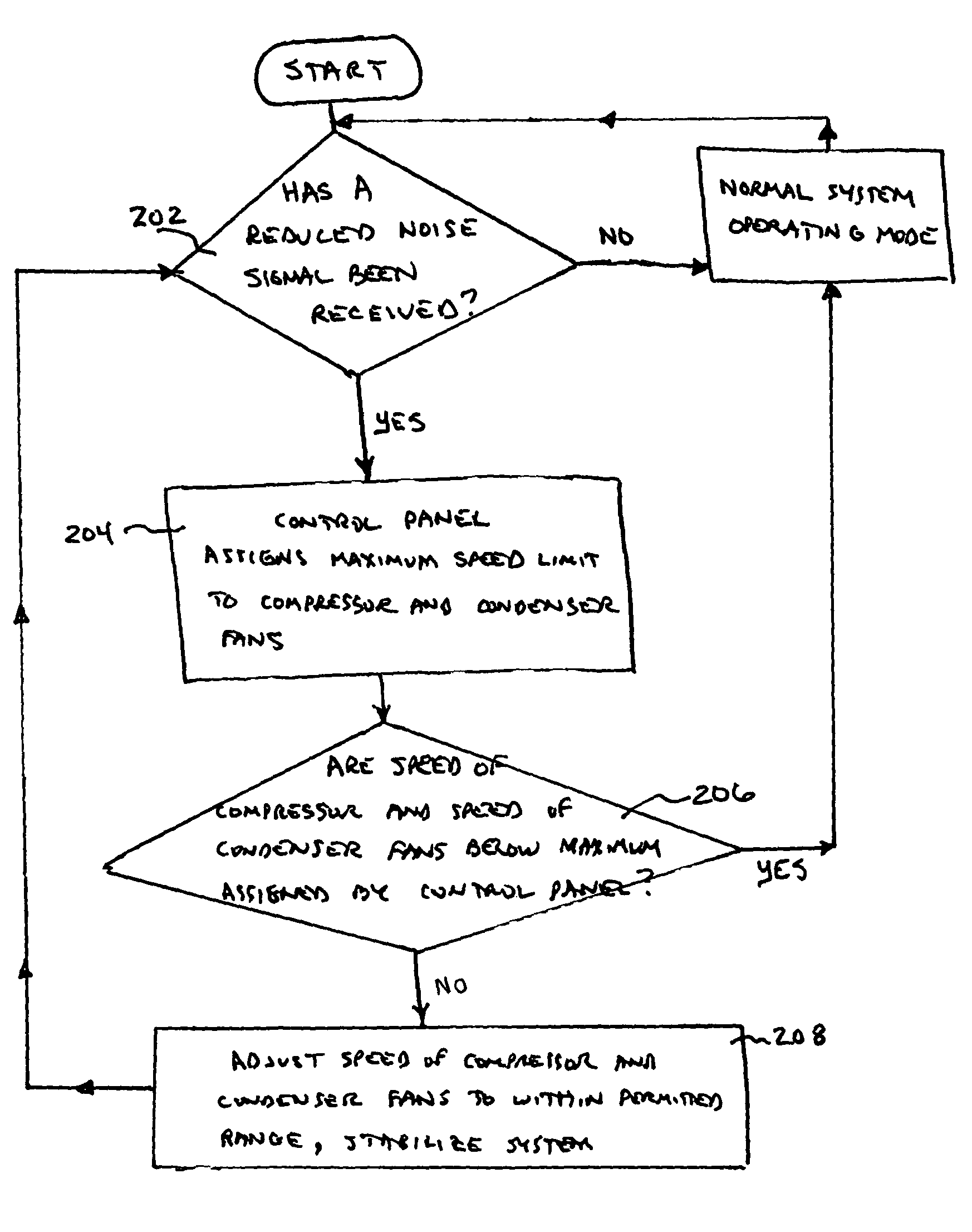
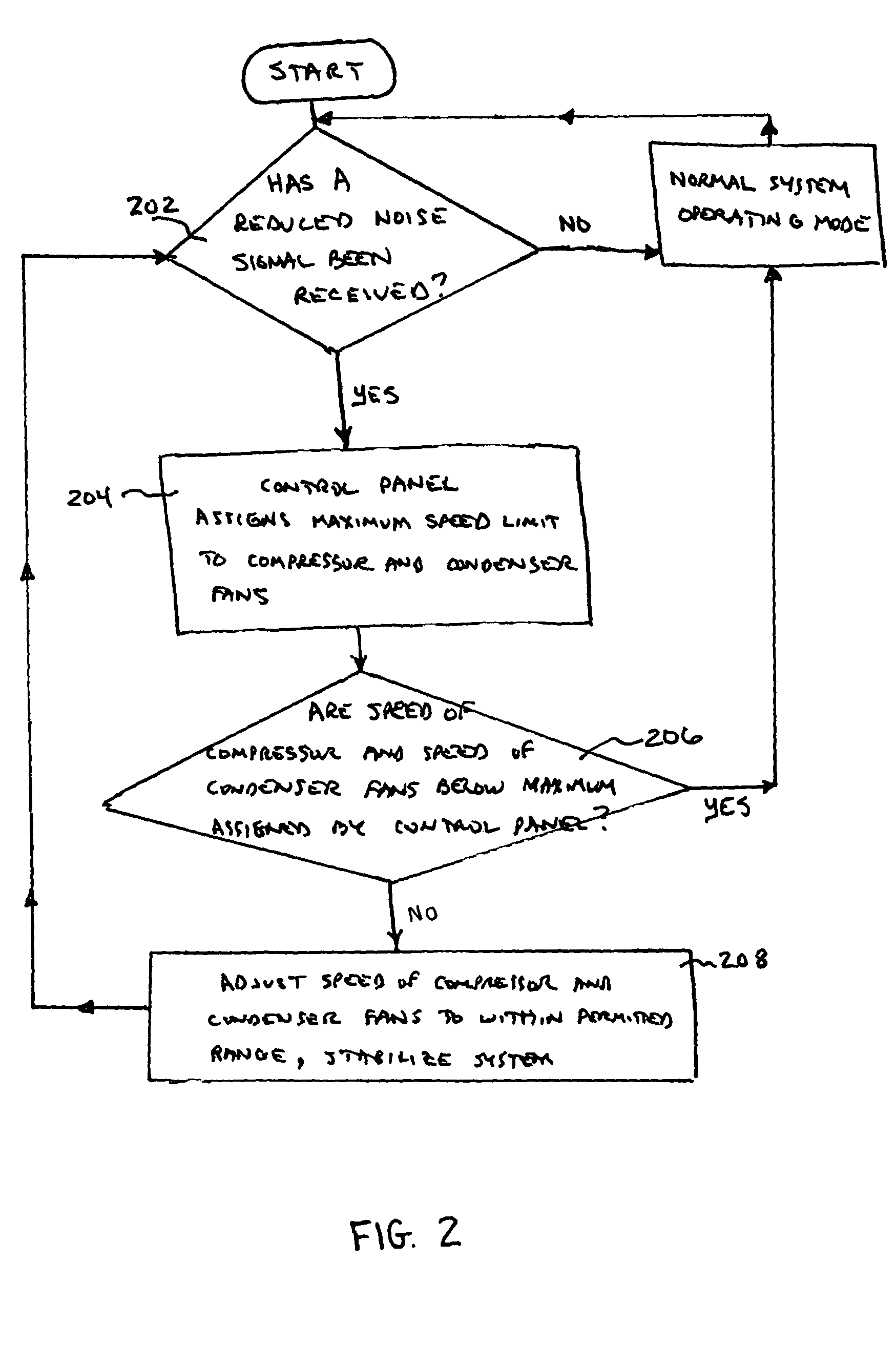
A noise control method is provided for a cooling system having at least one refrigerant circuit. The refrigerant circuit includes a compressor, a condenser, at least one condenser fan, and an evaporator. Noise control is only performed periodically in response to requirements for reduced operation at predetermined times. The request for reduced noise triggers the commencement of the noise control method. The noise control method involves reducing the operating speed of the compressor, as well as reducing the operating speed of at least one condenser fan, to within a predetermined range of allowable reduced operating speeds. The noise control method temporarily overrides the ability of the cooling system to fully respond to increased cooling or heating demands. When the noise control method is terminated, such as by the end of the stated period of time requiring reduced noise generation, the system is restored to normal operation, and remains fully responsive to cooling and heating demand until commencement of the next period of reduced noise requirements.

Description

CROSS-REFERENCES TO RELATED APPLICATIONS[0001]This application claims the benefit of U.S. Provisional Application No. 60 / 561,435 filed Apr. 12, 2004.BACKGROUND OF THE INVENTION[0002]The present invention relates generally to a sound reduction control system and method for a cooling system. More specifically, the present invention relates to a system and method for reducing the sound generated by a compressor driven chiller system having a variable speed drive by selectively and controllably reducing the speed of the compressor, the speed of the condenser fans, or the number of operating condenser fans in the system.[0003]In chiller, HVAC or refrigeration systems, a refrigerant gas is compressed by a compressor and passed to a condenser where it exchanges heat with another fluid, such as the ambient air forced over condenser coils by one or more condenser fans. From the condenser, the pressurized refrigerant passes through an expansion device and then to an evaporator. An environment...

Claims


Application Information

Patent Timeline
Patent Type & Authority Patents(United States)
IPC IPC(8): F25B39/04F25B1/00F25D29/00F25B49/00F25B49/02F25D17/02F25D19/00
CPCF25B49/02F25B49/027F25B2500/12Y02B30/743F25B2600/111F25B2700/171Y02B30/741F25B2600/021Y02B30/70
Inventor CRANE, CURTIS CHRISTIANHILL, IV, FRANK HIGHLANDGRAYBILL, ANDREW JOHNCASPER, IAN MICHAEL
Owner JOHNSON CONTROLS TYCO IP HLDG LLP
Learn More