
Acoustic liner use of such a liner and method for manufacturing an acoustic liner

Inactive Publication Date: 2006-03-23
SAAB AB
View PDF15 Cites 28 Cited by
  • Summary
  • Abstract
  • Description
  • Claims
  • Application Information

AI Technical Summary

Benefits of technology

[0006] It is one object of the invention to provide an improved acoustic liner which provides more design flexibility compared to prior art liners in that the ability of optimizing the linear characteristics is improved. It is another object of the present invention to provide a liner which is linear not only with respect to flow variations but also with respect to temperature variations. It is yet another object of the invention to provide a liner which can withstand high temperatures and especially which can be used in hot stream areas of aircraft engines.
[0014] The acoustic liner according to the present invention has a number of advantages over the prior art. Firstly, it can withstand hot stream environments. Further, its three-dimensional structure increases the design freedom and possibility of optimizing the linear properties (acoustic behavior) compared to what is possible with prior art liners. Especially, the developed liner technology allows liner designs with acoustic characteristics that are independent of both flow and temperature. Moreover, the inventive acoustic liner is linear and capable of attenuating sound in a broad frequency band. This is a very important feature of an acoustic liner for use in hot engine exhaust areas, e.g. aircraft engines and other applications wherein the noise has a relatively broad spectra. However, the invention is equally applicable to suppression of noise in cold applications, such as engine inlets. The inventive acoustic liner is light in weight and the cost of manufacture and mounting would be comparable to the costs for liners existing today. Especially the embodiment with a compressed top layer constitutes a very simple and cost-effective way of fine-tuning and optimizing the acoustic liner to a specific application and it allows for using pre-manufactured “off-the shell” top sheets in a variety of applications.

Problems solved by technology

The aircraft engines are the most significant contributors to the total aircraft noise during take-off and landing.
However, in practice it would be almost impossible to design a weave pattern such that the liner is capable of attenuating a broad frequency band.
Further, the liner can not withstand high temperatures, and therefore can not be used in hot stream areas of aircraft engines.
As stated above, today there are no linear liners available for use in hot stream areas of aero engines, since current liner technology regarding linear liners for engine intakes (“cold stream”) does not meet the thermal and other functional requirements for the engine exhaust areas.
These drawbacks of current liner technology have the effect that the noise environment around airports cannot be improved further as regards hot stream aero engine noise such as combustion noise.

Method used


Image

  • Acoustic liner use of such a liner and method for manufacturing an acoustic liner
  • Acoustic liner use of such a liner and method for manufacturing an acoustic liner
  • Acoustic liner use of such a liner and method for manufacturing an acoustic liner

Examples


Embodiment Construction

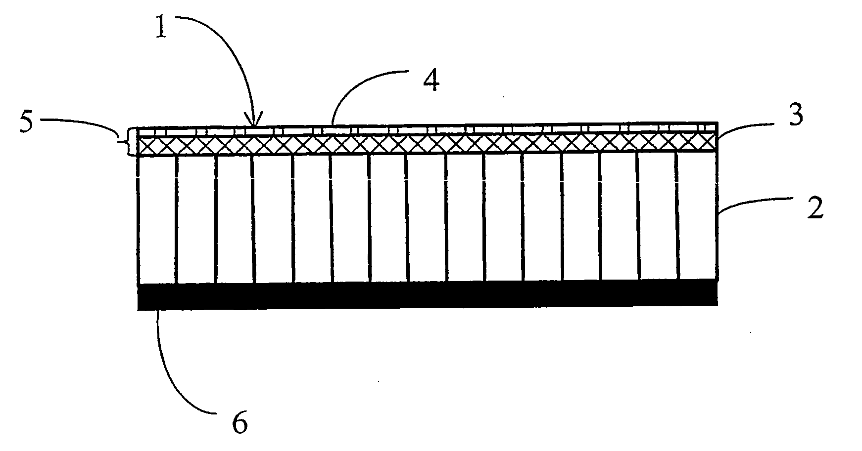
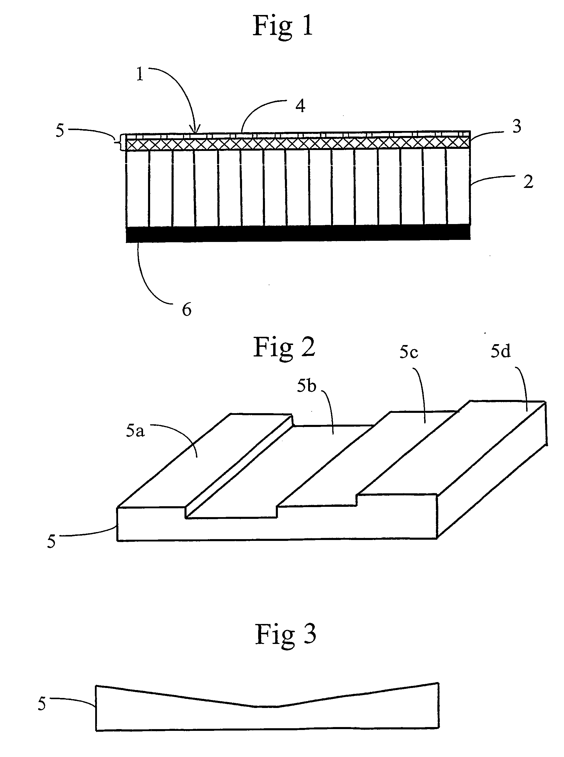
[0020] In the figure, a panel 1 is shown in the form of an acoustic liner. The panel 1 is designed to withstand hot stream environments and therefore can be used as a noise absorber for example in aircraft engine outlets. The panel also can be used in other hot environments such as in gas turbine applications.

[0021] The panel 1 comprises a liner core 2 and a top sheet assembly 5. The core 2 is attached to a solid backing sheet 6, which is impervious. The top sheet assembly 5 includes a layer 3 of a metallic foam and a perforated sheet 4. The liner core 2 is for example a conventional honeycomb core made of Titanium, Nickel or Chromium, or an alloy including one or more of said metals. However, the honeycomb core can be made of any metal or metal alloy withstanding the hot stream environment (typically about 700° C. of an aircraft engine). Alternatively, the line core 2 can be made of a metallic foam. Metallic foams will be described more in detail below. The thickness of the liner ...


PUM


Abstract

The present invention relates to an acoustic liner (1) arranged to attenuate sound. The acoustic liner (1) comprises a top sheet (5) having substantially linear characteristics and a liner core (2) or cavity. The top sheet (5) comprises a layer (3) of a metallic foam. The invention also relates to the use of said acoustic liner in a hot stream environment such as the outlet of an aircraft engine, and to the manufacture of an acoustic liner.

Description

FIELD OF THE INVENTION [0001] The present invention relates to an acoustic liner and the manufacture of such acoustic liner. It also relates to use of said acoustic liner in a hot stream environment, especially in the hot area of an aircraft engine. BACKGROUND OF THE INVENTION [0002] The noise due to aircraft is of critical concern to communities living around airports. The aircraft engines are the most significant contributors to the total aircraft noise during take-off and landing. The contributing sources of engine noise are fan, compressor, combustor, turbine and jet. It is known to use acoustic liners in the engine inlets of commercial short- medium- and long-range passenger and freight aircraft in order to reduce fan noise. The acoustic liners should preferably be linear since the linear liners are acoustically more efficient than conventional liners as the acoustic characteristics of the linear liners are not sensitive to changing flow and changing sound pressure levels preva...

Claims


Application Information

Patent Timeline
IPC IPC(8): E04B1/82F02K1/82G10K11/172
CPCF02K1/827Y02T50/671G10K11/172Y02T50/60
Inventor SARIN, SOHANNORDIN, PONTUS
Owner SAAB AB
Learn More