LED lamp device and method to retrofit a lighting fixture

a technology of led lamps and retrofitting efforts, which is applied in the manufacture of electric discharge tubes/lamps, lighting and heating apparatus, lighting support devices, etc., can solve the problems of loose efficiency, cost and inconvenience of removing conventional, non-led-based light fixtures and installing new, and retrofitting efforts often fail to address one or more of the functional differences characteristic of led lamps. , to achieve the effect of high thermal conductivity, light weight and high thermal conductivity

Active Publication Date: 2010-03-16
LSI INDS
View PDF33 Cites 78 Cited by
  • Summary
  • Abstract
  • Description
  • Claims
  • Application Information

AI Technical Summary

Benefits of technology

[0006]The material of construction of the LED lamp device is typically a metal or engineering plastic having a high thermal conductivity. Metals are typically selected from aluminum, copper, brass, bronze, iron and steel. Aluminum is particular attractive for its high thermal conductivity, light weight, availability, and low cost. The shaped outer surface of the LED lamp device provides proper fitting of the LED lamp assembly into the lighting fixture, and provides a heat-transferring interface over substantially the entire outer surface of the adapter sleeve, to dissipate heat away from the LED module and its power and control units.
[0010]The LED lamp device, and its use in a retrofitable retrofitting light fixture, can comprise an adapter sleeve having the annular outer wall with the shaped outside surface, and 2) a lamp head moveably affixed to the adapter sleeve that comprises a means for affixing the LED module. Typically the lamp head has an annular base portion having a proximal rim that associates with a shoulder on the annular wall of the adapter sleeve both to provide a broad contact interface for conducting heat through and away from the lamp head to the adapter sleeve, and to permit movement, typically rotation, of the lamp head with respect to the adapter sleeve, and more typically so that the LED module revolves around an axial centering line of the adapter sleeve. The LED module has a centerline disposed at an angle from the axial centering line of the adapter sleeve of from about 10° to about 70°.

Problems solved by technology

One drawback of LED lighting systems is the cost and inconvenience of removing conventional, non-LED-based light fixtures and installing new light fixtures that are design and optimized for LED-based lamps.
Nevertheless, such retrofitting efforts often fail to address one or more of the functional differences characteristic of LED lamps.
In particular, LED lamps are sensitive to heat generated by the LED itself, and may loose efficiency unless the heat and local temperature increases are minimized.
Furthermore, typical power convertors that convert off-line (110-377V AC) to 24V, constant current to drive the LEDs, are bulky and do not conveniently install into such socket-type light fixtures.

Method used


Image

  • LED lamp device and method to retrofit a lighting fixture
  • LED lamp device and method to retrofit a lighting fixture
  • LED lamp device and method to retrofit a lighting fixture

Examples


Embodiment Construction

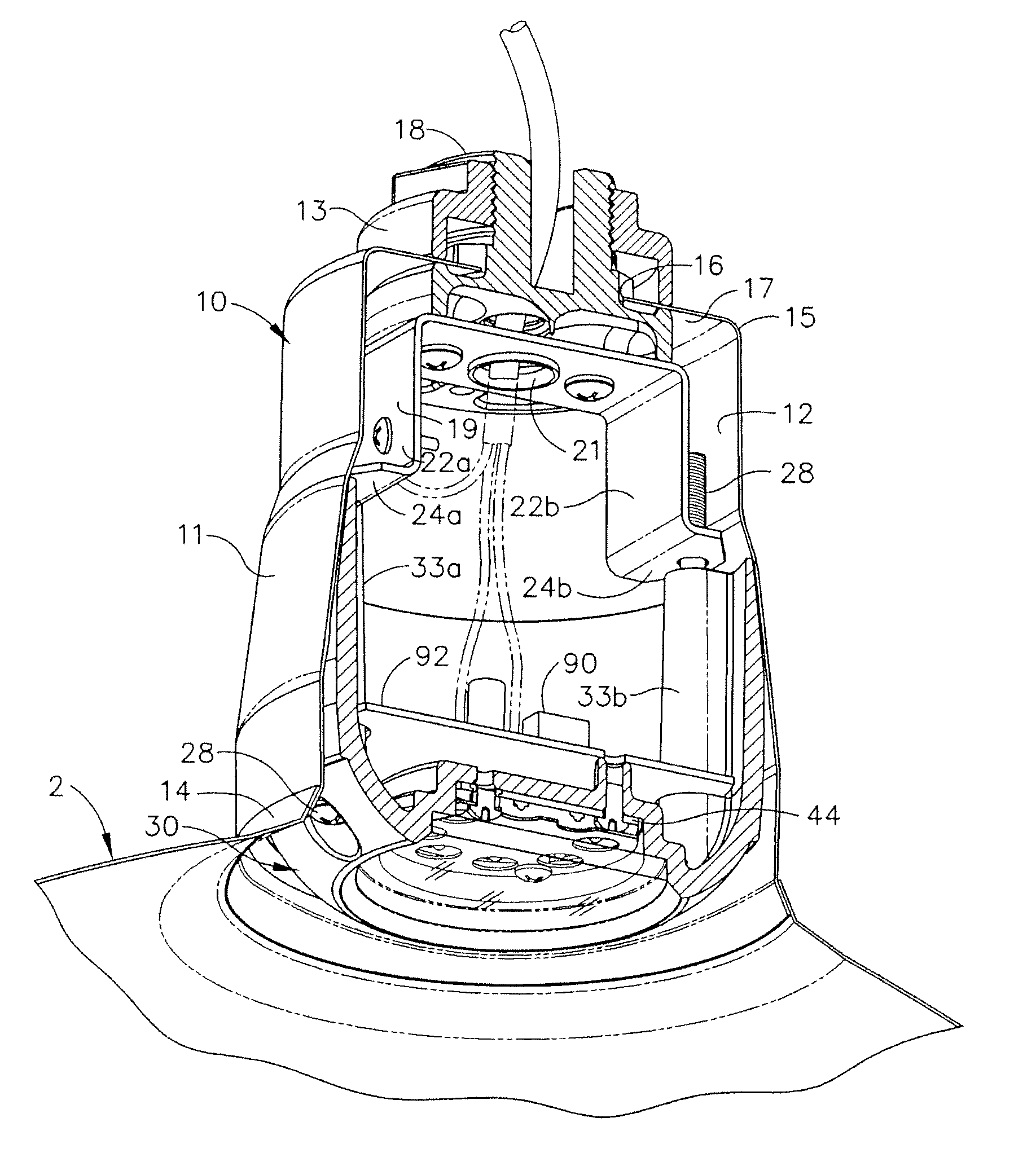
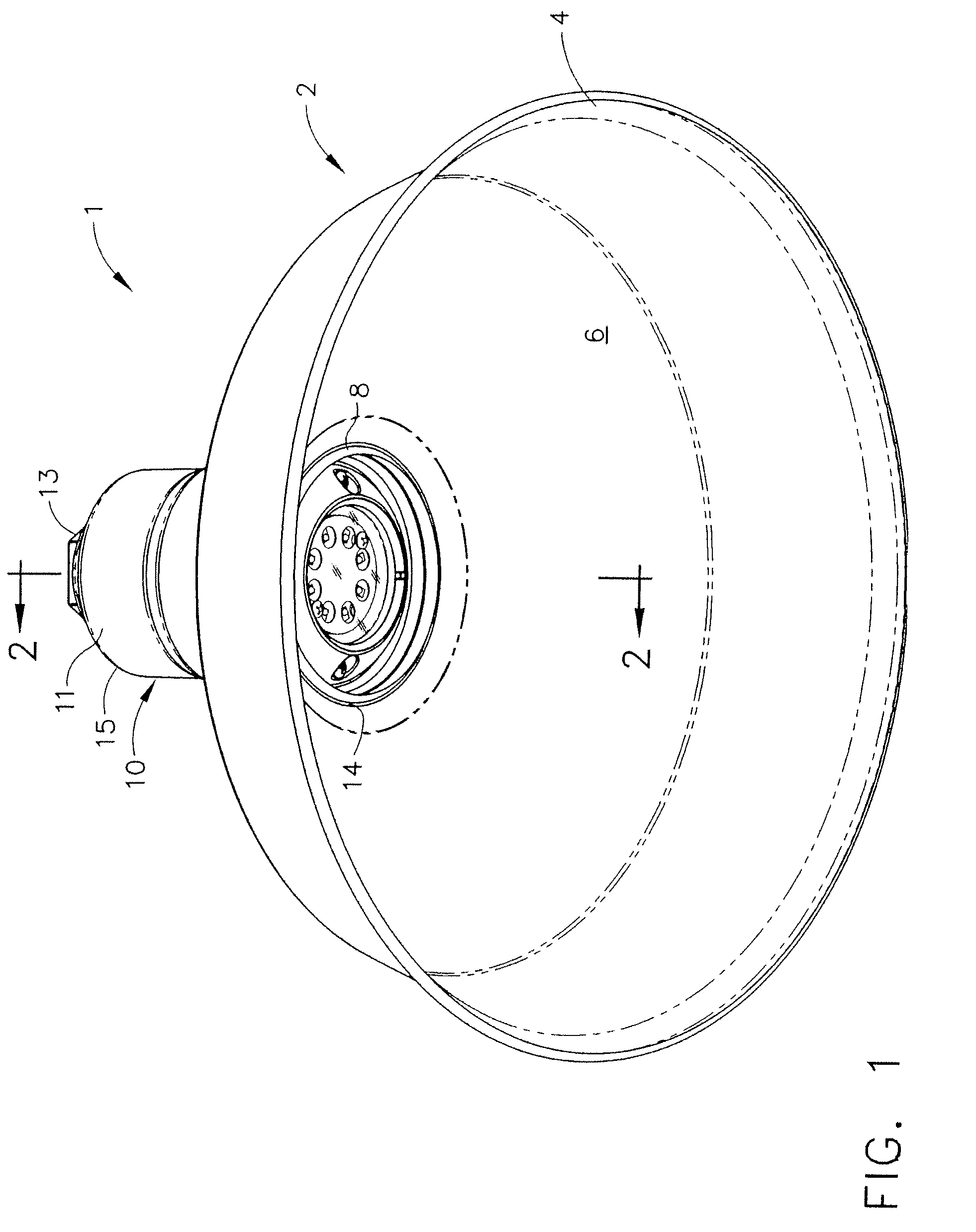
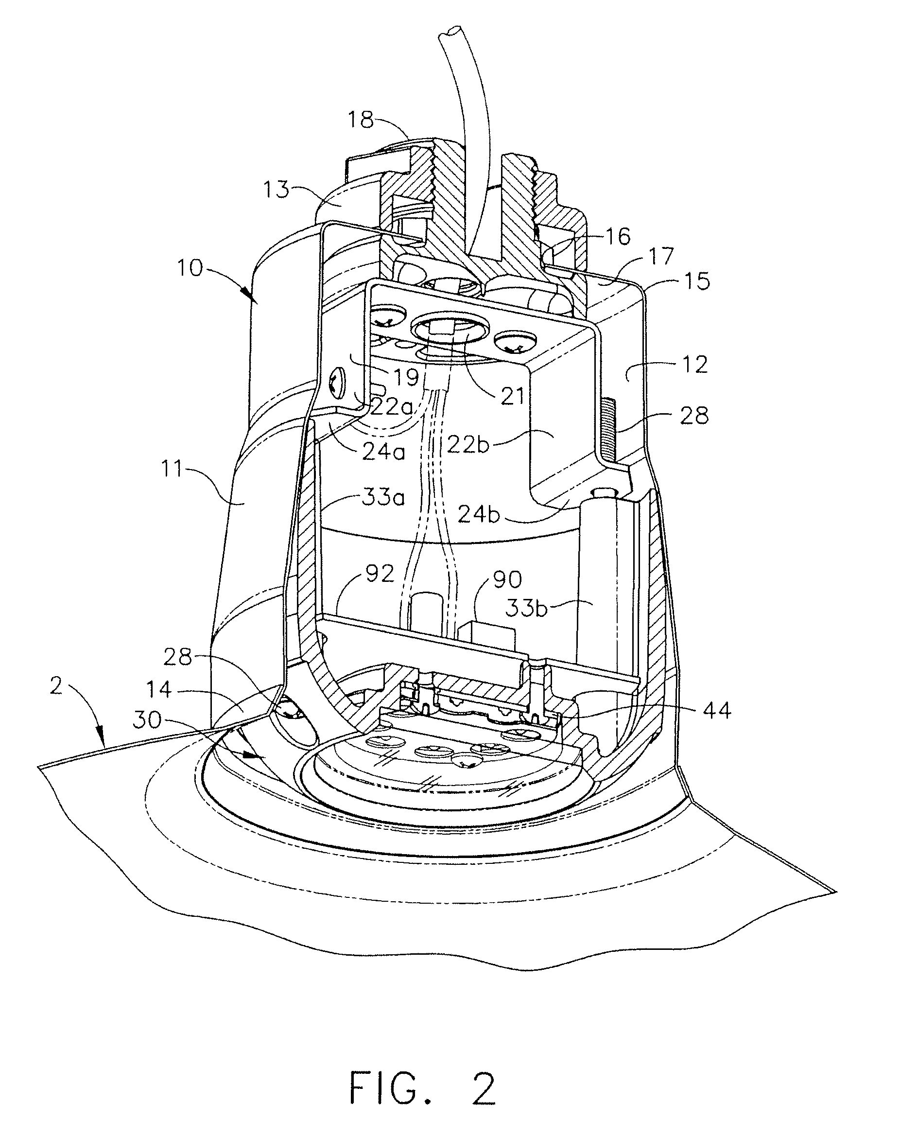
[0034]A typical LED-based lamp fixture is shown in FIGS. 1 and 2. The light fixture 1 includes a shade 2 and a collar 10. The shade 2 has a frustoconical shade wall 6 that defines a distal rim 4 and a proximal rim 8 that associates with the collar 10. The collar 10 has an annular outer wall 11 having an inner surface 12. The outer wall 11 is generally a cylindrical shape, though more typically having one or more sidewall portions that taper outwardly from a proximal end 15 to the distal end. The shade 2 is typically fixed to the outer distal rim 14 of the collar 10.

[0035]As shown in FIG. 2, the base 17 located at the proximal end 15 of the collar has an opening 16. The securing means is shown as an adapter 18 that extends through the opening 16 of the base 17 of the collar, and has an opening there through and a first end. The first end is secured, such as with threads, to an electrical conduit or cord (not shown) associated with the structure, such as a light pole, fence, and build...


PUM


Abstract

A device and method for retrofitting a light fixture from use with a lamp socket that employs a conventional incandescent or metal halide lamp, to use with a light emitting diode (LED)-based lamp assembly. The lamp fixture has a collar with a base and an annular outer wall extending out from the base. The LED lamp device includes a neck base having an annular outer wall having a shaped outside surface that is placed into direct surface contact with the inner surface of the annular outer wall of the collar, to establish an effective heat-transferring interface. The shaped outer surface of the neck base provides proper fitting of the LED lamp device into the lighting fixture, and provides a heat-transferring interface over substantially all of the outer surface of the neck base, to dissipate heat away from the LED module. Aluminum material provides high thermal conductivity, light weight, availability, and low cost.

Description

BACKGROUND OF THE INVENTION[0001]Outdoor lighting has evolved over the years from the earliest use of incandescent lamps, through the use of fluorescent, high intensity discharge (HID), and mercury-vapor lamps, and more recently to light emitting diode (LED) lamps. LED lamps offer several advantages, including improved quality, performance, lifespan and cost, and their use and popularity have been growing. LED lighting also provides, and has the potential for further providing, reduced power consumption per unit lumen.[0002]One drawback of LED lighting systems is the cost and inconvenience of removing conventional, non-LED-based light fixtures and installing new light fixtures that are design and optimized for LED-based lamps. To defray this expense, attempts have been made to retrofit, or force-fit, LED lamp technology into non-LED lamp fixtures. Examples include the incorporation of LED lamps inside and on the outside surface of “bulb” style lamps, with threaded electrical connect...

Claims


Application Information

Patent Timeline
Patent Type & Authority Patents(United States)
IPC IPC(8): F21V29/00
CPCF21K9/00F21V19/00Y02B20/383F21Y2115/10Y02B20/30
Inventor BOYER, JOHN DELMORE
Owner LSI INDS
Why Eureka
Try Eureka