Clip comprising a pin and a bush

a technology of pins and bushes, applied in the field of plastic clips, can solve the problems of increasing the cost of forming pins, poor operating efficiency, and the likelihood of deterioration of the coupling force between the workpiece and the attachment component, and achieve the effect of reducing the longitudinal length of the bush

Active Publication Date: 2010-03-16
NEWFREY
View PDF27 Cites 24 Cited by
  • Summary
  • Abstract
  • Description
  • Claims
  • Application Information

AI Technical Summary

Benefits of technology

[0007]It is therefore an object of the present invention to provide a clip capable of reducing a longitudinal length of a bush while allowing an intended portion of the bush to be largely and reliably expanded, so as to cope adequately with the need for setting a fastened position in a narrow range in a longitudinal direction of the bush, and performing a fastening operation in a state after a pin is pre-assembled to the bush.
[0011]According to this embodiment of the clip of the present invention, the pin is forcibly inserted into the opening in a direction orthogonal to the axial direction of the bush so as to be pre-assembled to the bush in the non-fastened position. A fastening operation can be performed after the pin is pre-assembled to the bush. By axially pushing the pin, the wide region of the protruding portion of the pin shank enlarges the opening of the bush body to expand the entire bush body in a radially outward direction. A longitudinal length of the entire bush can be reduced while allowing an intended portion of the bush body to be largely and reliably expanded, so as to cope adequately with the need for setting the fastened position in a narrow range in a longitudinal direction of the bush.
[0014]Further, the above clip may include stop means which is provided between an outer surface of the first large-diameter region of the rod portion of the pin shank and an inner surface of the bush body, and adapted to prevent the pin shank from being pulled out of the bush body in a radially outward direction when the pin is in the fastened position relative to the bush, so as to keep the pin in the fastened position.

Problems solved by technology

Thus, it is necessary to have a relatively long bush, which is unfavorable in a situation where a fastened position has to be set in a narrow range in the longitudinal direction.
In the clip disclosed in the Patent Document 2, the pin has the head formed in a particular shape, increasing the cost of forming the pin.
Moreover, the pin and the bush in the clip disclosed in the Patent Document 2 are not designed to be pre-assembled to one another, and therefore a fastening operation has to be performed while paying attention to preventing the pin and the bush from separating from one another, resulting in poor operating efficiency.
Further, as with the clip disclosed in Patent Document 1, this clip is designed to expand an outer diameter of the bush over the entire longitudinal length of the bush, and therefore it is necessary to have a relatively long bush, which is unfavorable in the situation where the fastened position has to be set in a narrow range in the longitudinal direction.
The clip disclosed in the Patent Document 3 is not designed to largely and reliably expand an intended portion of the bush, and therefore deterioration in coupling force between the workpiece and the attachment component is likely.
Moreover, due to difficulty in reliably expanding an intended portion of the bush, the clip disclosed in Patent Document 3 is required to have a relatively long bush, which is unfavorable in the situation where the fastened position has to be set in a narrow range in the longitudinal direction.

Method used


Image

  • Clip comprising a pin and a bush
  • Clip comprising a pin and a bush
  • Clip comprising a pin and a bush

Examples


Embodiment Construction

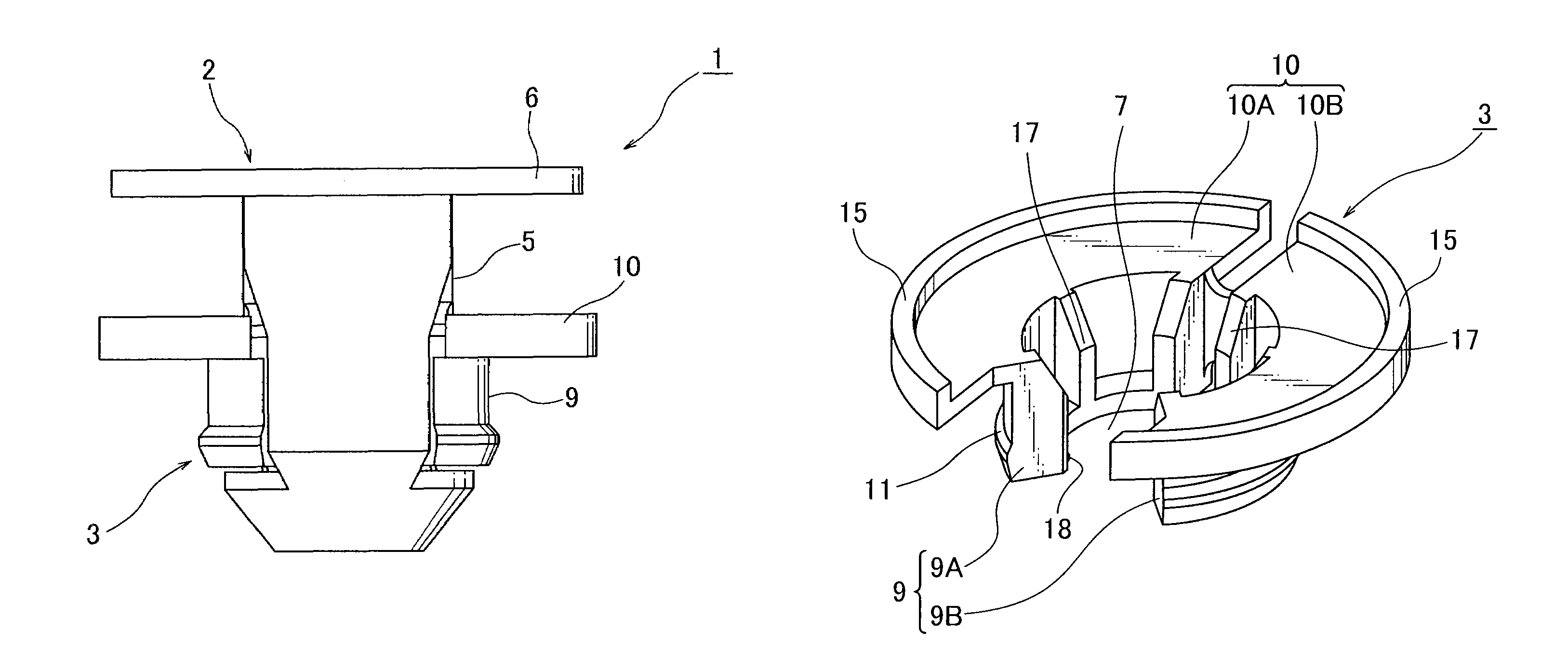
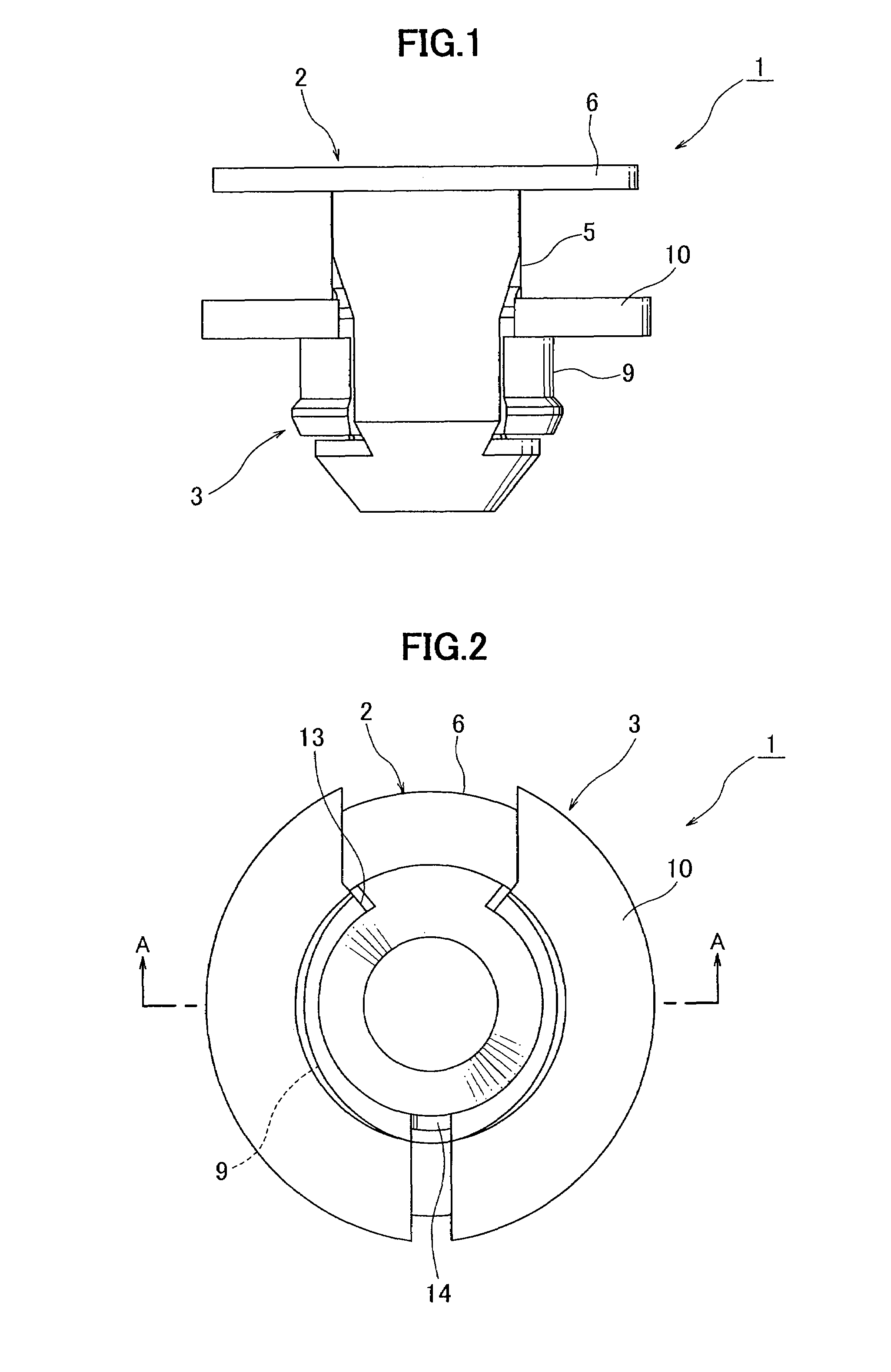
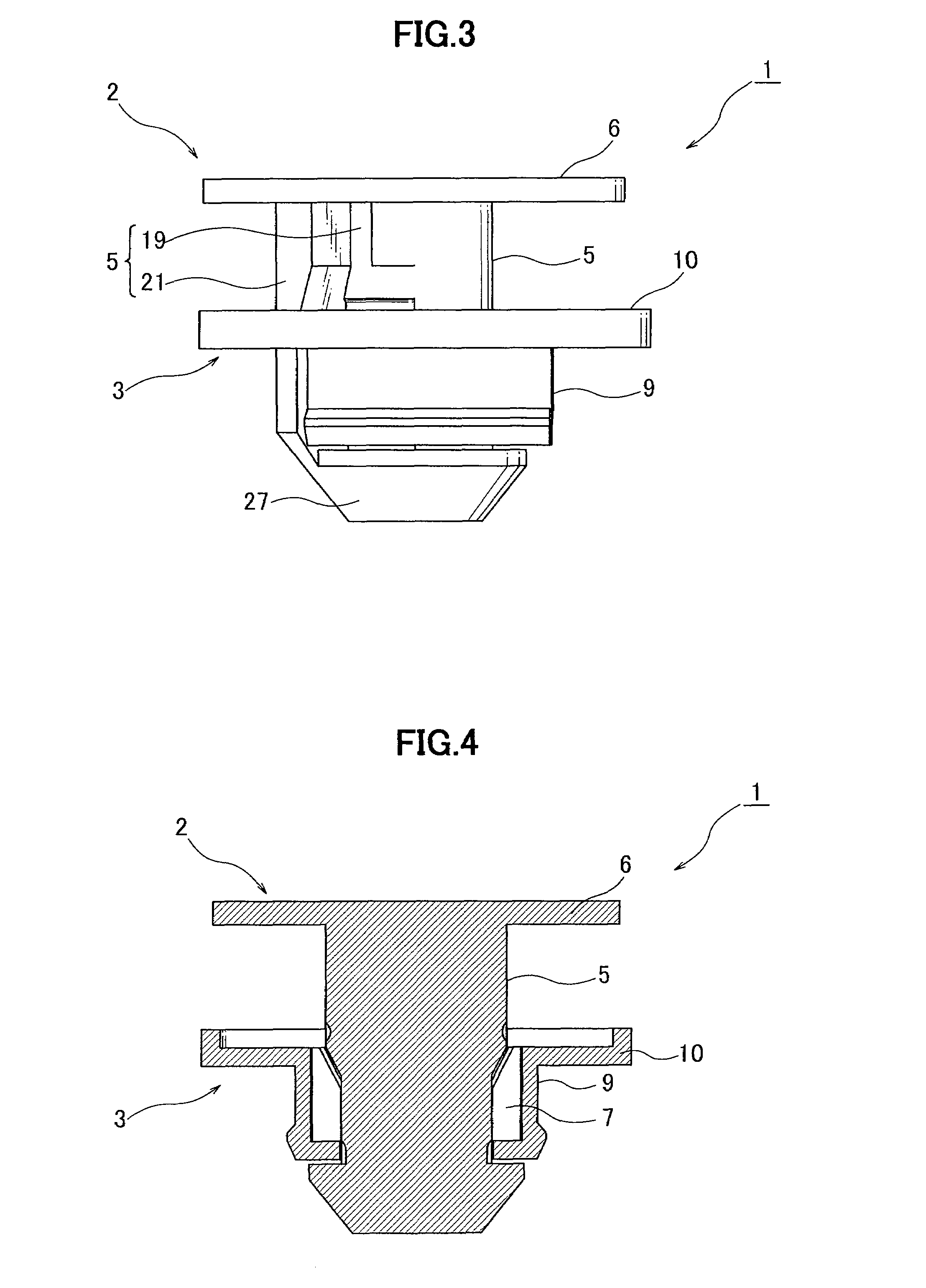
[0038]In reference to the drawings, a clip 1 according to one embodiment of the present invention will now be described. As shown in FIGS. 1 to 4, the clip 1 comprises a pin 2 and a bush 3 which are pre-assembled to one another. The pin 2 is made of a hard plastic and formed by an integral molding process, and the bush 3 is made of a hard plastic and formed by an integral molding process. The pin 2 includes a pin shank 5, and a pin flange 6 formed at a first end (upper end in FIGS. 1, 3 and 4) of the pin shank 5. The bush 3 includes a generally annular-shaped bush body 9 having a hollow portion 7 formed to receive the pin shank 5 of the pin 2, and a bush flange 10 formed at a first end (upper end in FIGS. 1, 3 and 4) of the bush body 9. The pin 2 is adapted to be received in the hollow portion 7 of the bush body 9 of the bush 3 so as to be pre-assembled in a non-fastened position, causing no expansion in an outer diameter of the bush body 9, and then moved from the non-fastened posi...


PUM


Abstract

A clip comprises a pin, and a hollow bush adapted to receive the pin therein. The bush includes a flange and a bush body having an opening which is formed by partially cutting off a peripheral wall thereof and adapted to receive therein a pin shank in a direction orthogonal to an axial direction of the bush body. The bush body and the bush flange are adapted to be expanded in a radially outward direction of the bush body about a position opposed to the opening, in a hinged manner. The pin has a shank that includes a protruding portion which has a narrow region formed near a distal end of the pin shank, causing no expansion in an outer diameter of the bush body in the radially outward direction when the pin is in a non-fastened position, and a wide region adjacent to the bush flange, causing an expansion in the outer diameter of the bush body when the pin is in a fastened position.

Description

CROSS-REFERENCE TO RELATED APPLICATION[0001]This application claims the benefit of Japanese Patent Application 2006-153729 filed Jun. 1, 2006, incorporated herein by reference.BACKGROUND OF THE INVENTION[0002]The present invention relates to a plastic clip which comprises a pin, and a bush adapted to receive the pin therein and allow an outer diameter thereof to be expanded by pushing the pin into the bush, and more specifically to a plastic clip suitable for coupling an attachment component to a workpiece, such as a panel of an automobile body.[0003]There has been known a plastic clip comprising a pin, and a bush having a hollow portion formed to receive the pin therein, wherein the pin has a shape formed to be received into the hollow portion of the bush and axially moved from a non-fastened position, causing no expansion in an outer diameter of the bush, to a fastened position, causing an expansion in the outer diameter of the bush by a pushing operation. For example, Japanese Ut...

Claims


Application Information

Patent Timeline
Patent Type & Authority Patents(United States)
IPC IPC(8): F16B13/06
CPCF16B19/1081F16B41/002Y10T16/05Y10T24/3424
Inventor SANO, TAKAHIRO
Owner NEWFREY
Why Eureka
Try Eureka