
Double visual-interface socket

Inactive Publication Date: 2010-03-16
COMPUPACK TECH +1
View PDF2 Cites 17 Cited by
  • Summary
  • Abstract
  • Description
  • Claims
  • Application Information

AI Technical Summary

Benefits of technology

[0012]Hence, the double visual-interface socket according to the present invention uses the circuit board and the adapter module to connect signals at the terminal pins of the upper socket unit to a solder surface at a bottom portion of the double visual-interface socket, thereby minimizing the lengths of the terminal pins of the upper socket unit. By doing so, the characteristic impedance of the finished product will comply with related specifications so as to ensure the transmission quality of high-frequency video signals.

Problems solved by technology

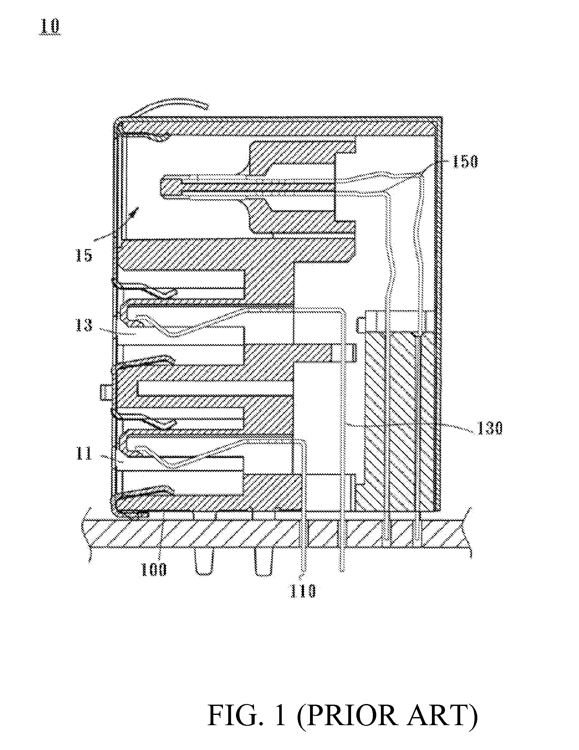
However, if the aforesaid design of the conventional stacked-type sockets is applied to a double visual-interface socket, the terminal pins of the upper socket unit must be extended so as for bottom ends of these terminal pins, as well as those of the lower socket unit, to reach a solder surface at a bottom portion of the socket; as a result, the characteristic impedance of the resulting double visual-interface socket do not comply with related specifications.
A mismatch of impedance between components will result in signal reflection, which in turn leads to production of noise and signal interference.
As the lengths of terminal pins are a major factor in the characteristic impedance of a double visual-interface socket, it is a challenge faced by all socket designers to overcome the problem of impedance mismatch caused by the conventional stacked-type socket design.

Method used


Image

  • Double visual-interface socket
  • Double visual-interface socket
  • Double visual-interface socket

Examples


Embodiment Construction

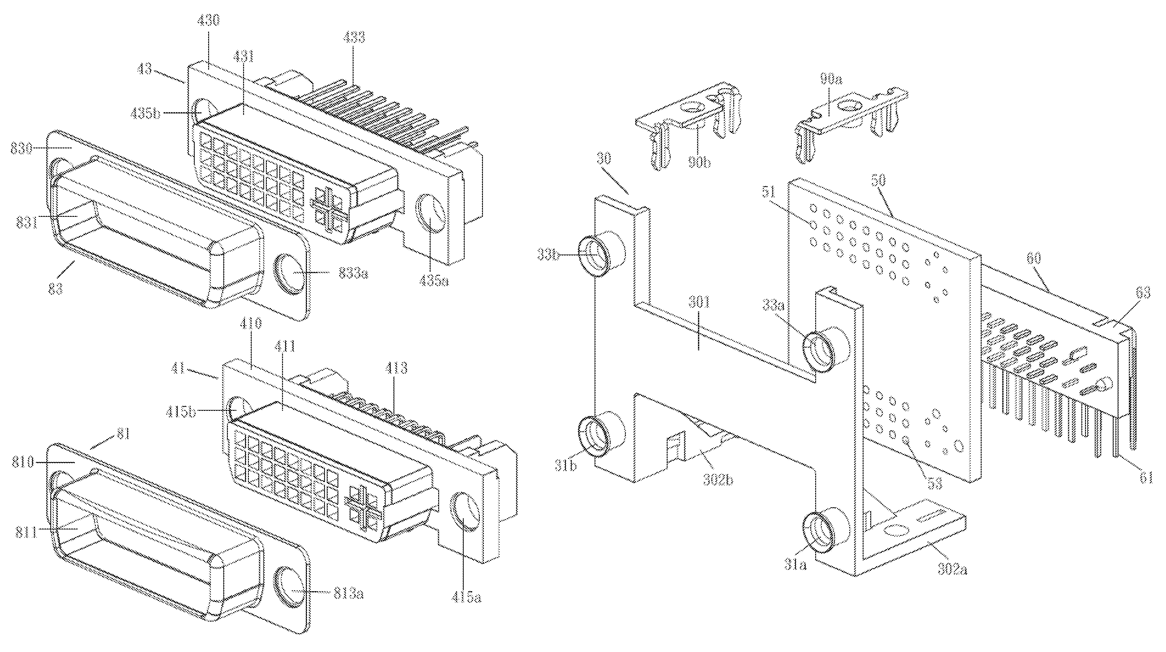
[0018]The present invention provides a double visual-interface socket including two socket units stacked up, wherein both socket units comply with the DVI standard. The features of the present invention are described herein by way of the DVI-I Dual-Link type sockets depicted in the accompanying drawings.

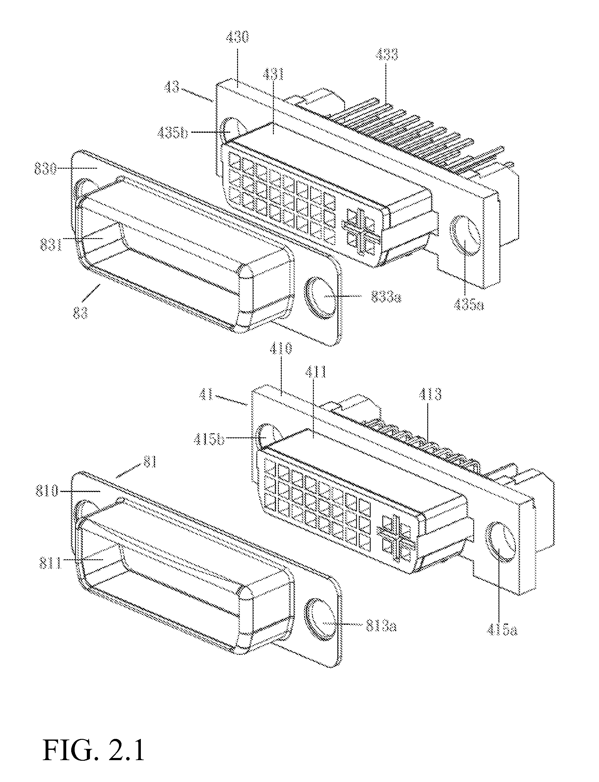
[0019]Please refer to FIGS. 2 through 6 for an embodiment of the present invention. FIG. 2 and FIG. 3 are exploded perspective views of a double visual-interface socket according to the embodiment of the present invention when viewed from different angles. FIG. 4 and FIG. 5 are partially assembled views of the double visual-interface socket shown in FIGS. 2 and 3, when viewed from different angles. FIG. 6 is a perspective view of the double visual-interface socket according to the embodiment of the present invention.

[0020]As shown in the drawings, a double visual-interface socket 20 includes a frame 30, a lower socket unit 41, an upper socket unit 43, a circuit board 50, an adapter m...


PUM


Abstract

A double visual-interface socket compliant with socket design rules set forth in the Digital Visual Interface standard comprises: a lower socket unit including plural L-shaped terminal pins; an upper socket unit disposed above the lower socket unit and including plural terminal pins; an adapter module including plural L-shaped pins arranged in rows; and a circuit board having plural terminal guide holes and plural extension guide holes. The terminal guide holes are inserted by, soldered to, and therefore electrically connected with the terminal pins of the upper socket unit, respectively. The extension guide holes are electrically connected with the terminal guide holes, respectively, and are inserted by, soldered to, and therefore electrically connected with ends of the L-shaped pins of the adapter module, respectively. The opposite ends of the L-shaped pins of the adapter module are substantially aligned with bottom ends of the L-shaped terminal pins of the lower socket unit.

Description

BACKGROUND OF THE INVENTION[0001]1. Technical Field[0002]The present invention relates to an electronic connector and, more particularly, to a double visual-interface socket compliant with the Digital Visual Interface (DVI) standard.[0003]2. Description of Related Art[0004]With the advancement of technology, computer peripherals have become so diversified that the number of sockets provided in a computer must increase accordingly. In consequence, the so-called composite or stacked-type sockets were developed, wherein a plurality of sockets are stacked together three-dimensionally and integrated into a single socket, thereby not only reducing the footprint of the otherwise multiple sockets on a motherboard or interface card, but also simplifying the pin insertion procedure.[0005]Please refer to FIG. 1 for a sectional view of a conventional stacked-type socket 10. The stacked-type socket 10 includes a housing 100. Socket units 11, 13, 15 are stacked in the housing 100 and include term...

Claims


Application Information

Patent Timeline
IPC IPC(8): H01R13/60
CPCH01R12/712H01R12/7029H01R25/006H01R27/02
Inventor CHEN, MARKLU, CHING-TUNG
Owner COMPUPACK TECH
Learn More