Oscillator circuit

a technology of oscillator circuit and oscillator pulse, which is applied in the direction of oscillator generator, pulse technique, pulse generator, etc., can solve the problems of inability to control the phase of the injected current pulse in optimal, more parasitic capacitance, and inability to counteract fast switching, etc., to achieve low parasitic capacitance, high frequency, and fast switching characteristics

Active Publication Date: 2010-03-16
TELEFON AB LM ERICSSON (PUBL)
View PDF4 Cites 10 Cited by
  • Summary
  • Abstract
  • Description
  • Claims
  • Application Information

AI Technical Summary

Benefits of technology

[0009]The objects of the present invention are to provide an oscillator with fast switching characteristics and current pulse optimisation. The presented invention allows realization in a very compact (and low parasitic) way. The characteristics will further allow very high frequency VCOs based on this topology.
[0010]Thus, the invention according to a preferred embodiment will provide a faster or / and more optimised switching resulting in lower oscillator phase noise for a fixed bias current.

Problems solved by technology

However, increasing the power consumption is not desired and wider transistors will result in more parasitic capacitance, which counteracts fast switching.
Moreover, it is not possible to control the phase of the injected current pulse in an optimal way with the common oscillator topologies shown in FIGS. 1a and 1b.

Method used


Image

  • Oscillator circuit
  • Oscillator circuit
  • Oscillator circuit

Examples


Embodiment Construction

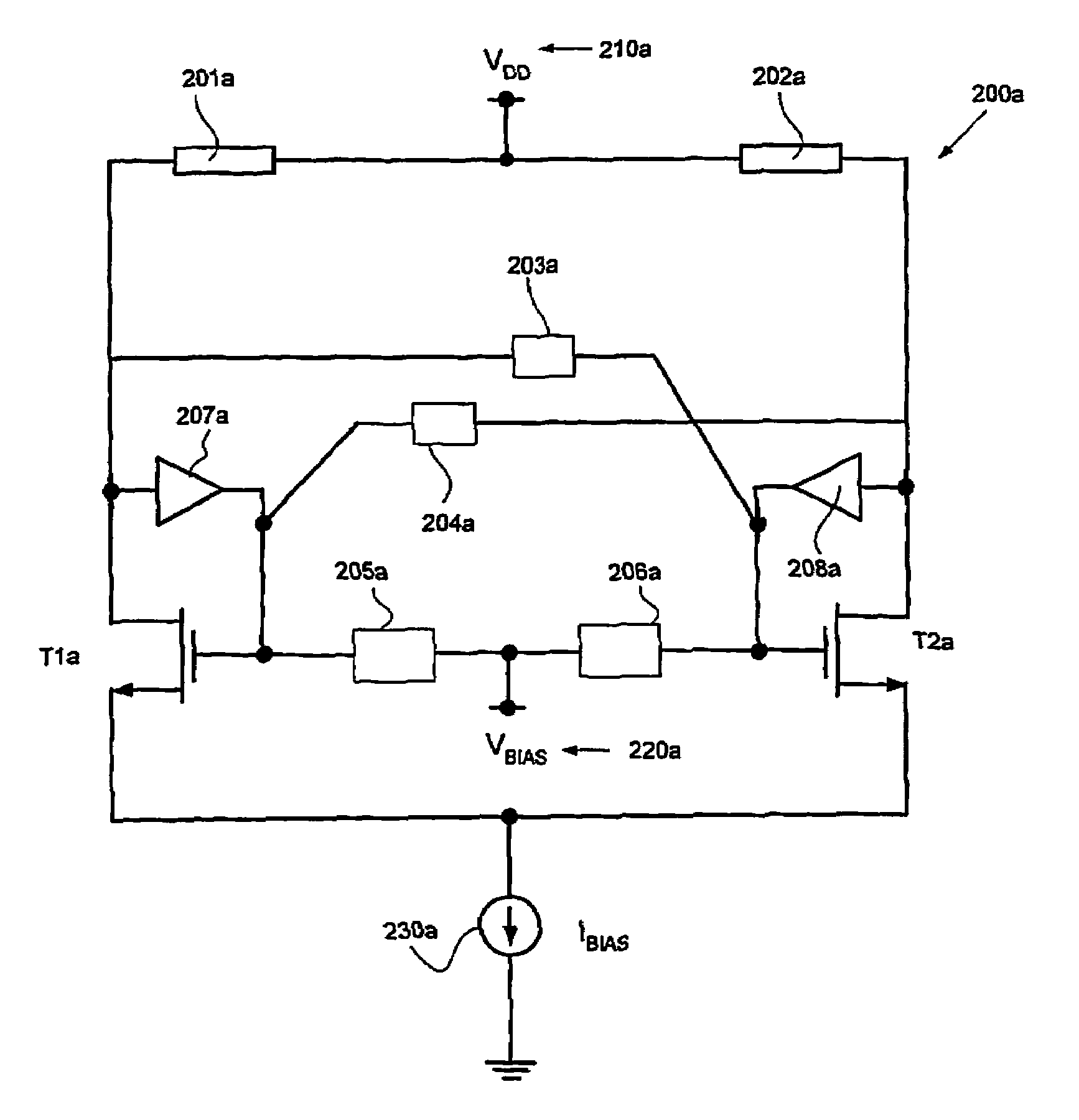
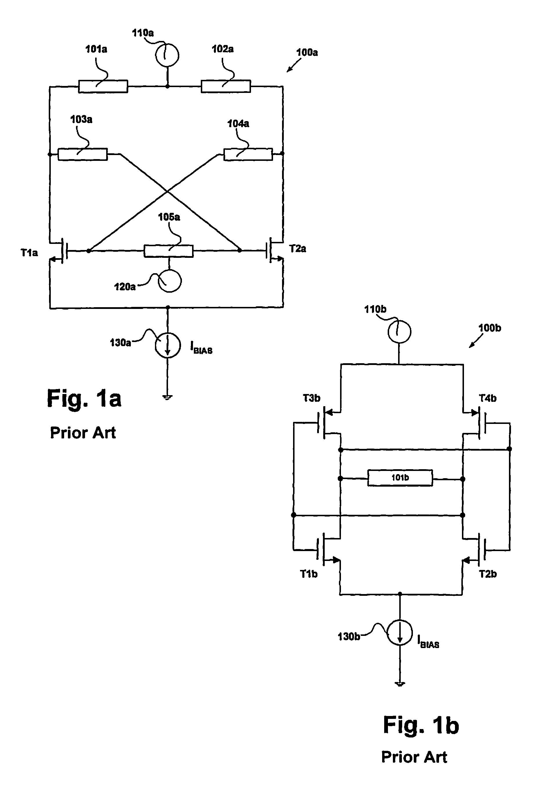
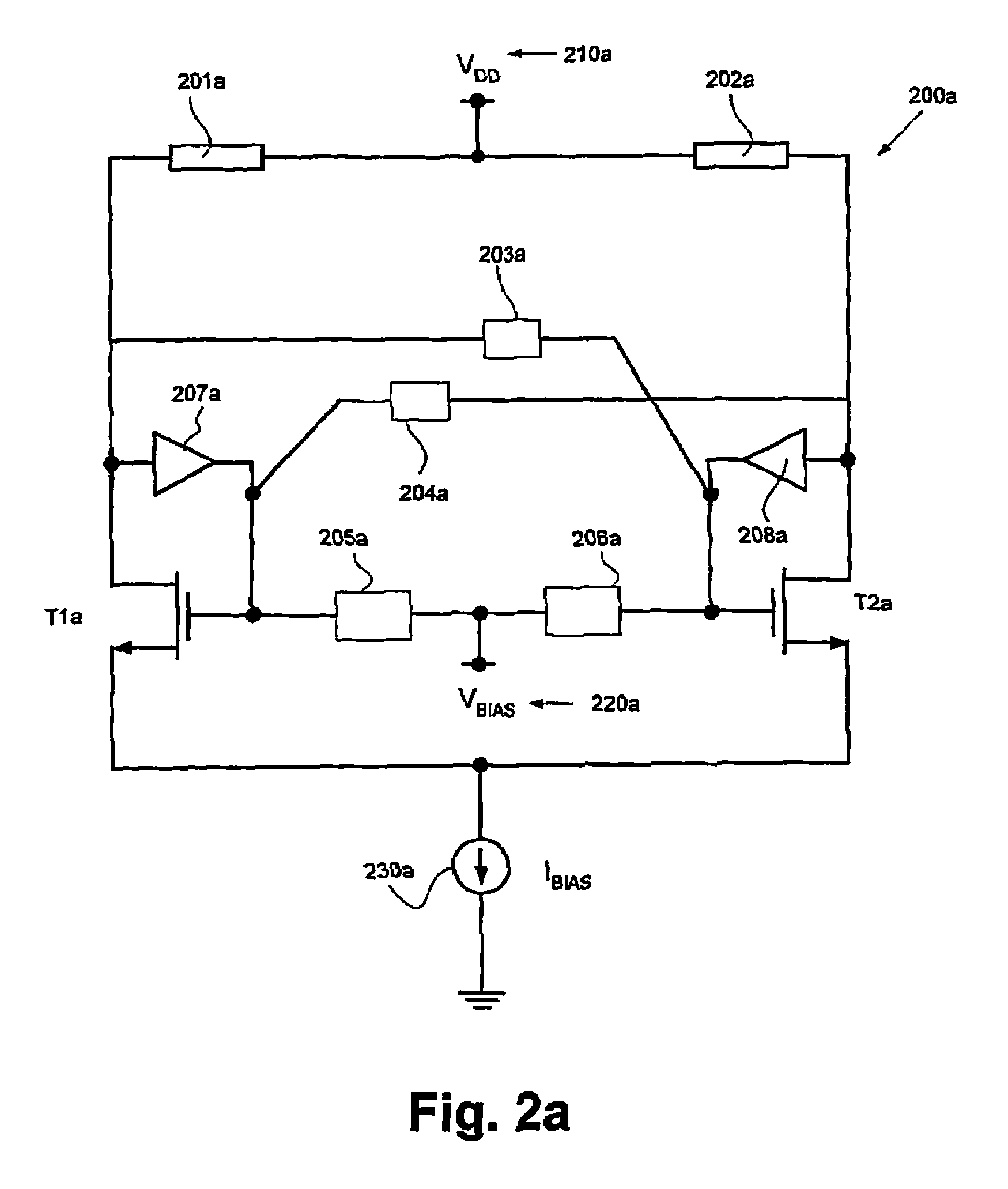
[0029]According to the invention, the circuits according to FIGS. 1a and 1b are modified and comprise additional positive feed-back loops with a device having variable gain and variable phase characteristics. By this optimisation a lowered phase noise for the oscillator can be achieved. The active device in the added loop will have a high impedance load, which provides extra voltage gain despite a low current consumption. This is illustrated in FIGS. 2a and 2b.

[0030]Thus, FIG. 2a illustrates an oscillator circuit 200a, according to one exemplary embodiment of the present invention, comprising two resonant elements 201a and 202a, which at a common terminal are fed from a supply voltage 210a (VDD) and connected to the drains of transistors T1a and T2a, respectively. Feedback elements 203a and 204a are connected in series between the drain of one of the transistors to the gate of each other transistor and vice versa. A voltage bias network comprising a source 220a feeding common termi...


PUM


Abstract

The present invention relates to an oscillator circuit having a resonant element, an active element, a feedback loop, and an additional loop comprising a phase shifting element.

Description

TECHNICAL FIELD OF THE INVENTION[0001]The present invention relates to an oscillating electrical circuit having multiple loops.BACKGROUND OF THE INVENTION[0002]The basic concept of a single ended oscillator comprising an active element A and the feedback element β is illustrated in FIG. 5. To start and maintain an oscillation in an electrical oscillator, normally the output of an active element is fed back to the input of the active device by a feedback network, which creates a loop-gain larger than one. The feedback elements have normally narrow-band characteristics. Moreover, the oscillation frequency for the oscillator may be varied by electrically controlling the centre frequency for the feedback element.[0003]This is further illustrated in FIGS. 1a and 1b for a differential realisation. To create an oscillator with low phase noise, fast switching of the active device(s) is / are advantageous. Moreover, the relation in time between the current injected by the active device into th...

Claims


Application Information

Patent Timeline
Patent Type & Authority Patents(United States)
IPC IPC(8): H03B5/12
CPCH03B5/1228H03B5/1215
Inventor ASPEMYR, LARSJACOBSSON, HARALD
Owner TELEFON AB LM ERICSSON (PUBL)
Why Eureka
Try Eureka