Echo canceler circuit and method

a canceler circuit and echo cancellation technology, applied in the field of communication systems, can solve problems such as limitations in algorithm echo modeling convergence rate, idle or significantly slower update procedure of echo canceler adaptive filter coefficient, and inability to solve the stable condition known as “howling”

Active Publication Date: 2010-03-16
CONTINENTAL AUTOMOTIVE SYST INC
View PDF22 Cites 9 Cited by
  • Summary
  • Abstract
  • Description
  • Claims
  • Application Information

AI Technical Summary

Problems solved by technology

An echo signal corresponding to the delayed transmitted uplink signal is perceived as annoying to the near end user and in some cases can result in a unstable condition known as “howling”.
When the near end user is not talking, then the echo canceler adaptive filter coefficient update procedure is typically idle since no downlink signal is present, however the filtering operation may still be active.
Again the echo canceler adaptive filter coefficient update procedure is typically idle or significantly slower due to the interference of the noise end signal sources.
One problem, however, is that real world effects including limitations in algorithm echo modeling convergence rates and steady state performance, variability in the echo path, mathematical precision limitations of a particular device employed, and non-linear audio system components, among others, all effect the ability of the adaptive echo canceller to remove or reduce the echo component from the transmit signal.
In vehicular environments, background noise may be generated as a result of driving at high speeds or on bumpy roads, operating a blower fan resulting in air turbulence over the microphone, lowering or raising a window resulting in wind rumble, operating windshield wipers, operating turn signals or performing other activities resulting in other sources of noise within the vehicle.
While noise suppression techniques may reduce background noise in a static or slowly changing noise environment, both noise suppression and echo cancellation performance can be significantly degraded by the combined generation of noise and echo signals.
Background noise is a persistent and common issue when echo cancellers are operating is harsh environments such as in an automobile environment.
The noise modulation effect introduced primarily due to the second echo canceler adaptive filter 84 can be quite rapid, and results in poor performance of the noise suppression module 20 such as reduced signal to noise ratio (SNR) as well as annoying noise artifacts introduced by the noise suppression module 20 itself.

Method used


Image

  • Echo canceler circuit and method
  • Echo canceler circuit and method
  • Echo canceler circuit and method

Examples


Embodiment Construction

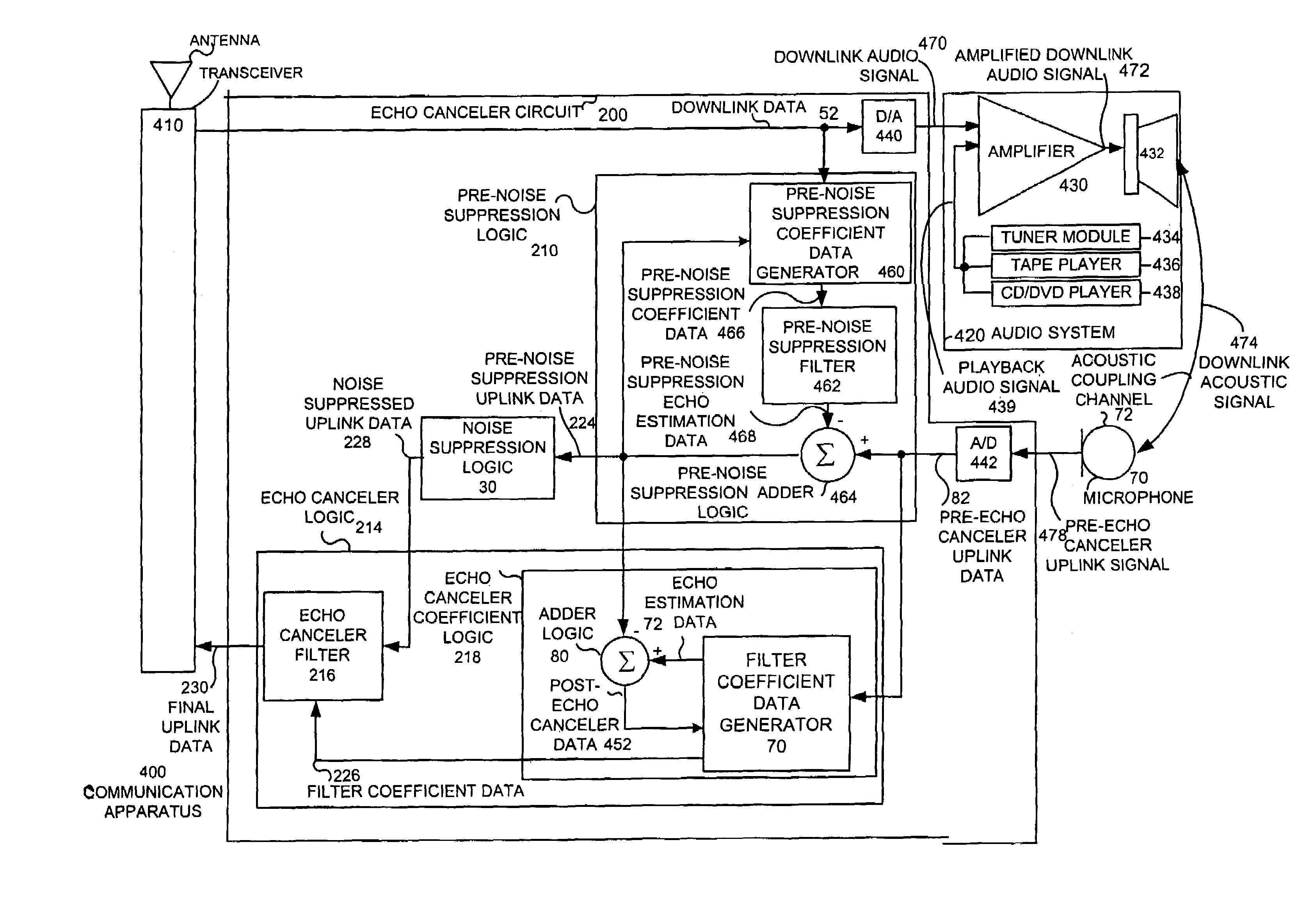
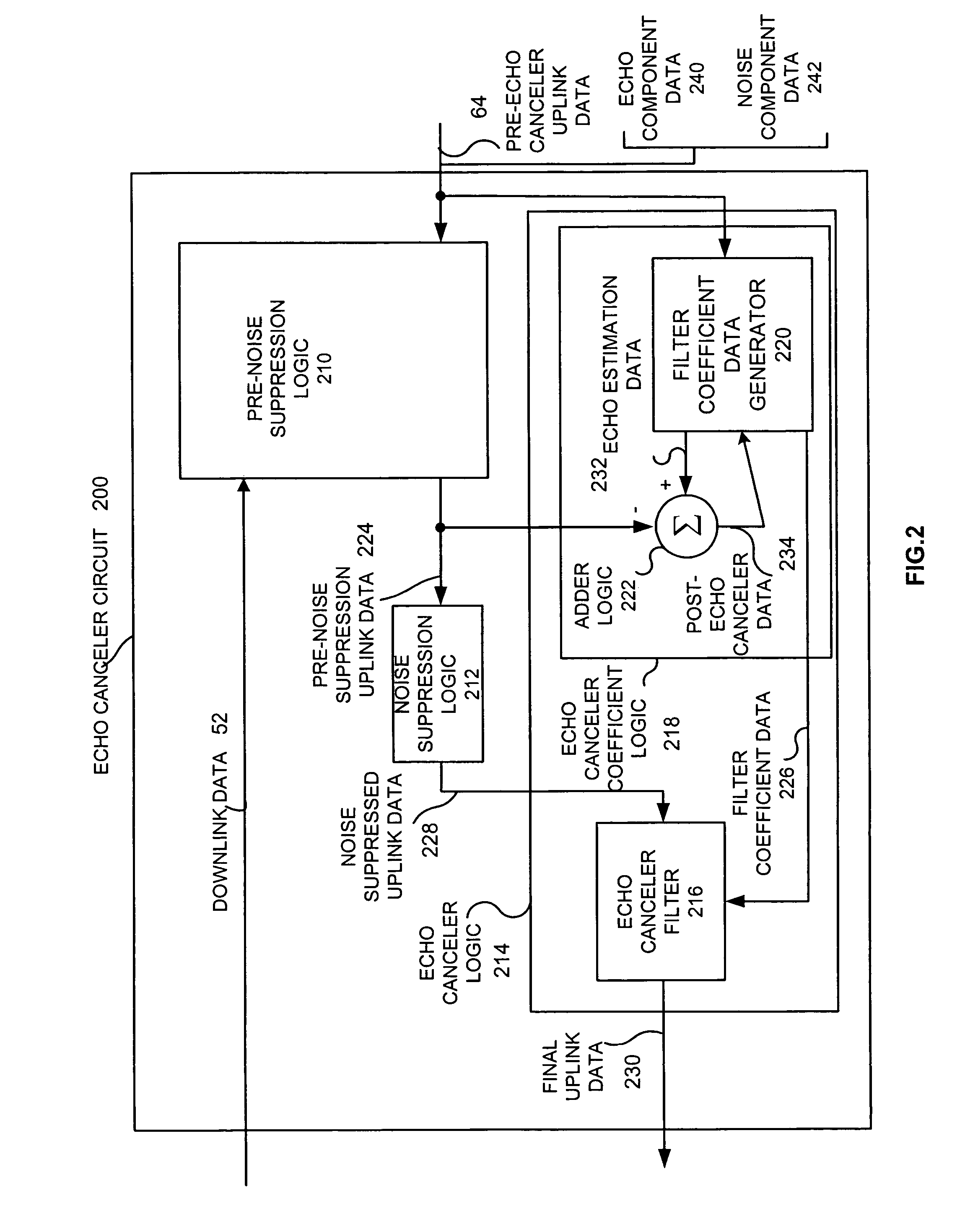
[0020]An echo canceler circuit and method performs echo cancellation and noise suppression in a non-interfering manner. The echo canceler circuit includes pre-noise suppression logic, echo canceler coefficient logic, noise suppression logic and an echo canceler filter. The pre-noise suppression logic receives pre-echo canceler uplink data and downlink data, and in response produces pre-noise suppression uplink data. The echo canceler coefficient logic receives the pre-noise suppression uplink data and the pre-echo canceler uplink data, and in response produces filter coefficient data. The noise suppression logic receives the pre-noise suppression uplink data, and in response produces noise suppressed uplink data. The echo canceler filter receives the noise suppressed uplink data and the filter coefficient data and in response produces final uplink data. The invention described herein presents a unique cascaded echo canceller filter and noise suppression topology that allows for incr...


PUM


Abstract

An echo canceller circuit (200) and method performs cascaded echo cancellation and noise suppression in a non-interfering manner. The echo canceller circuit (200) includes pre-noise suppression logic (210), echo canceller coefficient logic (218), noise suppression logic (212) and an echo canceller filter (216). The pre-noise suppression logic (210) receives pre-echo canceller uplink data (64) and downlink data (52), and in response produces pre-noise suppression uplink data (224). The echo canceller coefficient logic (218) receives the pre-noise suppression uplink data (224) and the pre-echo canceller uplink data (64), and in response produces filter coefficient data (226). The noise suppression logic (212) receives the pre-noise suppression uplink data (224), and in response produces noise suppressed uplink data (228). The echo canceller filter (216) receives the noise suppressed uplink data (228) and the filter coefficient data (226) and in response produces final uplink data (230).

Description

FIELD OF THE INVENTION[0001]The invention relates generally to communication systems and more particularly to echo cancelers and echo cancellation methods.BACKGROUND OF THE INVENTION[0002]Communications systems may employ echo cancelers to compensate for the effects of echo. These systems may also employ noise suppressors to compensate for the effects of noise in a communication environment.[0003]Echo in a communication system is commonly characterized as the return of a part of the transmitted uplink signal from an end user back to the originator of the transmitted signal after a delay period. The reflection of the transmitted signal may occur due to a number of reasons, such as an impedance mismatch in a four / two wire hybrid, or feedback from acoustic coupling in a telephone, wireless device or hands free speaker phone at the far end. An echo signal corresponding to the delayed transmitted uplink signal is perceived as annoying to the near end user and in some cases can result in ...

Claims


Application Information

Patent Timeline
Patent Type & Authority Patents(United States)
IPC IPC(8): H04M9/08H04B3/20
CPCH04M9/082H04B1/7107
Inventor PIKET, JAMES B.IWAI, KYLE K.ROKUSEK, DANIEL S.
Owner CONTINENTAL AUTOMOTIVE SYST INC
Why Eureka
Try Eureka