Locating mobile terminals

a mobile terminal and location technology, applied in the direction of instruments, measurement devices, electrical equipment, etc., can solve the problems of inability to use the above-described cell-based mobile location procedures suitable for gsm, failure of methods, and inability to meet the requirements of a w-cdma-type signalling system, so as to achieve the effect of reducing the error function

a mobile terminal and location technology, applied in the direction of instruments, measurement devices, electrical equipment, etc., can solve the problems of inability to use the above-described cell-based mobile location procedures suitable for gsm, failure of methods, and inability to meet the requirements of a w-cdma-type signalling system, so as to achieve the effect of reducing the error function

US7680501B2Inactive Publication Date: 2010-03-16NOKIA TECHNOLOGLES OY

Image

  • Locating mobile terminals
  • Locating mobile terminals
  • Locating mobile terminals

Examples


Embodiment Construction

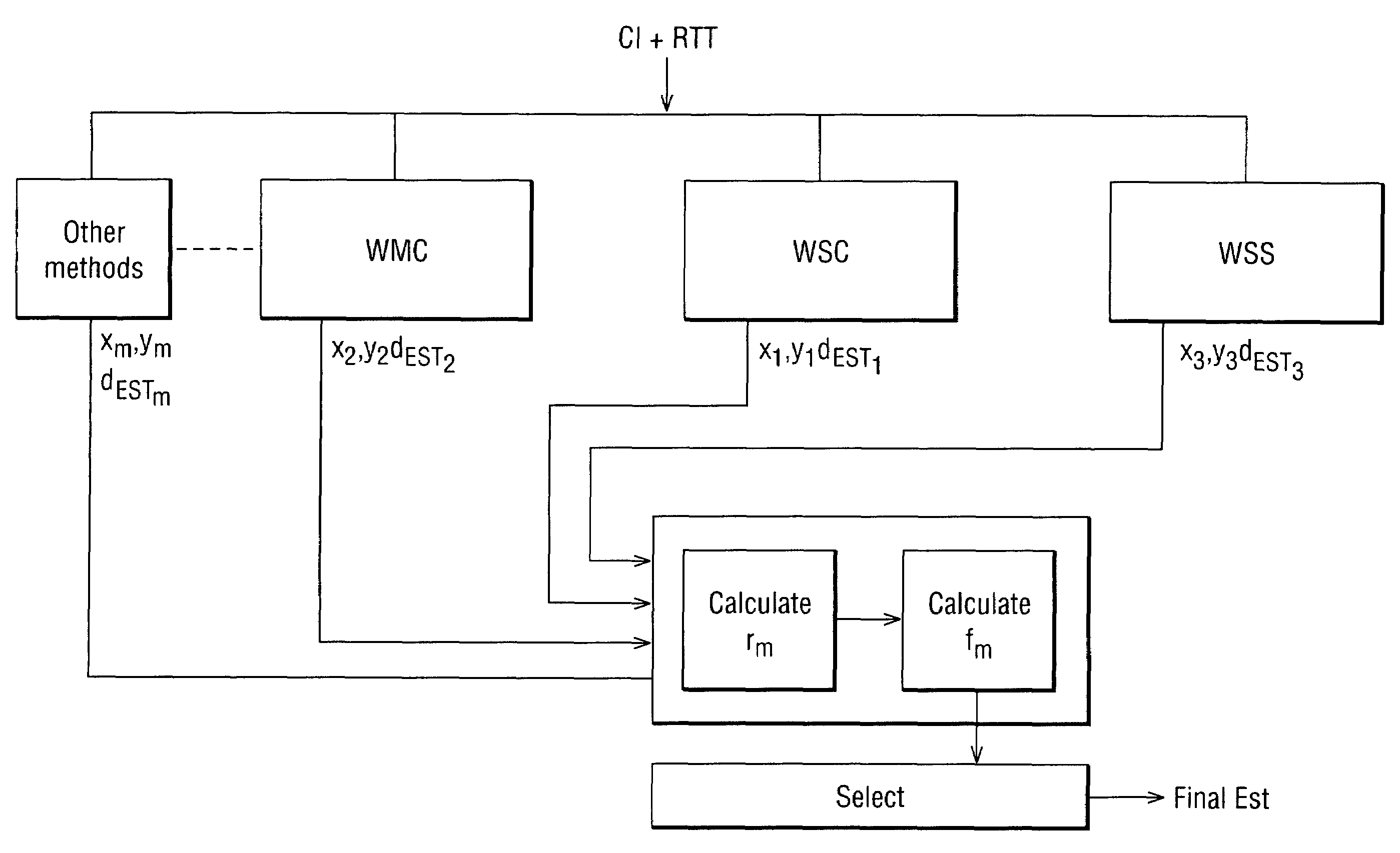
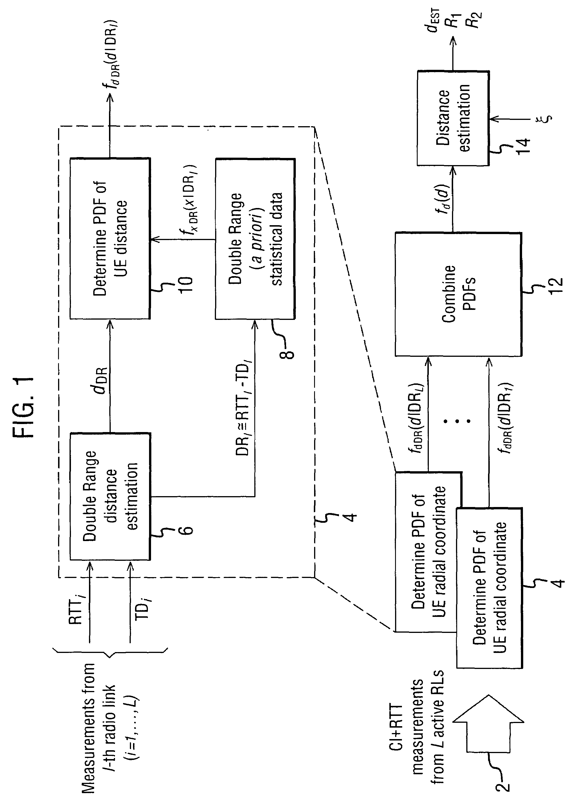
[0039]Before describing methods in accordance with embodiments of the present invention, a detailed description of one possibility for calculating a distance estimate will firstly be described with reference to FIG. 1, because this is an important component of the location methods discussed in the following. It will be appreciated however that other distance estimation techniques could be used.

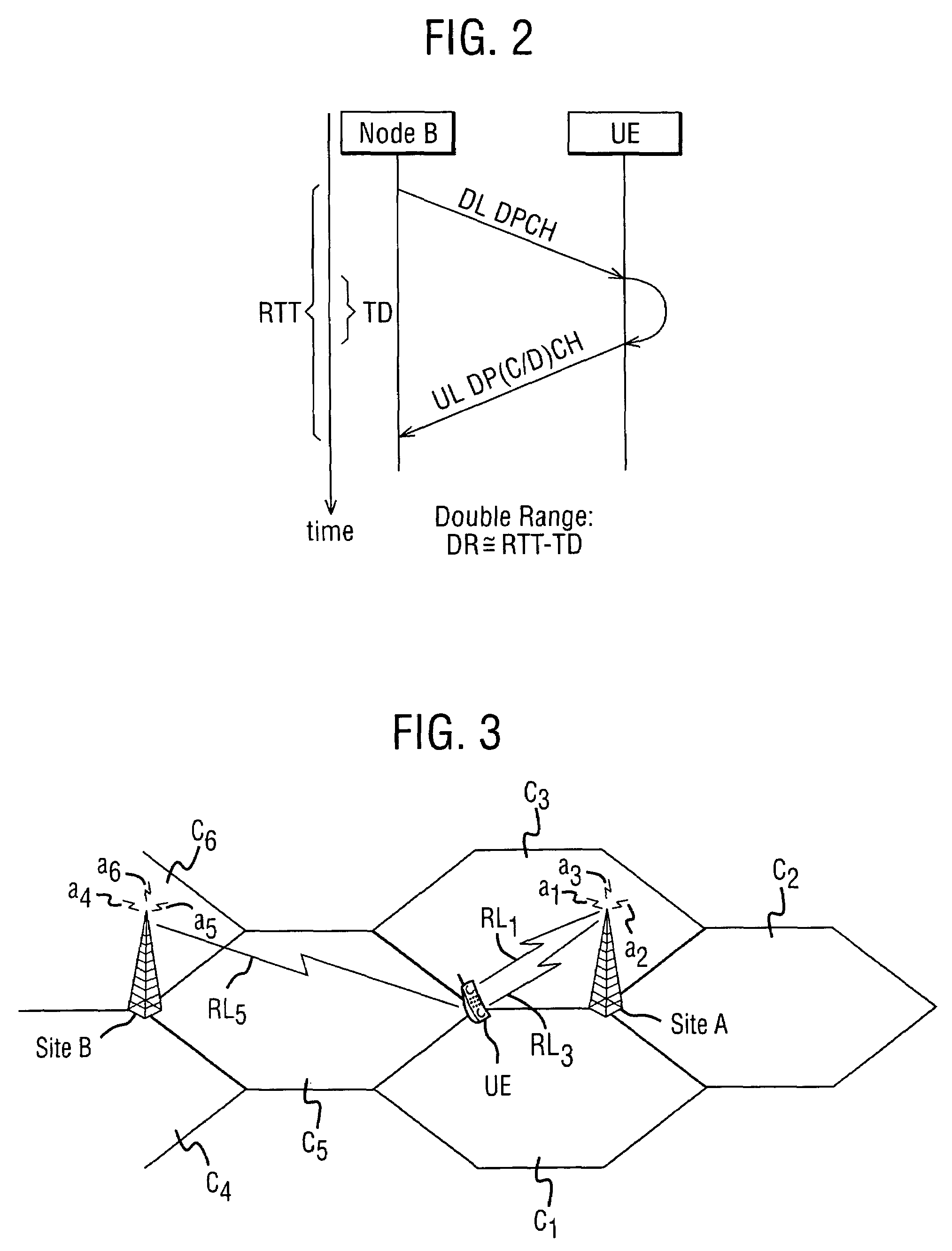
[0040]FIG. 1 is a schematic block diagram illustrating the blocks involved in a distance estimate calculation obtained from a set of measurement pairs of the round trip time (RTT) and Rx−Tx time difference (TD). FIG. 2 illustrates what these distances represent in a mobile communications network. FIG. 2 illustrates a user equipment UE which can be in the form of a mobile telephone or other mobile terminal and a Node B, which represents a base station in the universal telecommunications radio access network (UTRAN) system. A downlink dedicated physical channel signal labelled DL DPCH in FIG. 2 ...


PUM


Abstract

A method of providing a location estimate for a mobile station in a wireless communications network. The method of providing the location estimate includes implementing, in parallel, a plurality of different location estimate generation methods, each location generation method generating a location estimate. The method of providing the location estimate also includes selecting one of the location estimates based on predetermined criteria.

Description

FIELD OF THE INVENTION[0001]The present invention relates to a method and an apparatus for locating a mobile terminal in a communications network, particularly but not exclusively using multiple sources of information.BACKGROUND TO THE INVENTION[0002]The ability to pinpoint the location of mobile terminals is a desirable feature of a mobile telephone network. This is because of the need to provide customer services which rely on knowing the whereabouts of users of these services. For example, up-to-date local traffic information can be provided to enable a user to avoid nearby traffic jams. A user may also wish to know, for example, how to get to the nearest pub or restaurant from their present location. Clearly the location of the user must be ascertained to within even a few metres for this type of service to work.[0003]Another reason for wishing to know the location of a mobile terminal is so that emergency services can locate a caller who is unable to provide an accurate persona...

Claims


Application Information

Patent Timeline
16 Mar 2010
Publication
US7680501B2
IPC
H04W24/00; H04W36/18; H04W64/00
CPC
H04W64/00; H04W36/18; G01S5/0263
Inventors
SILLASTO, EERO; SPIRITO, MAURIZIO