Plow with blade wing

a blade wing and plow technology, applied in the field of plows, can solve the problems of increasing the cost, complexity, and weight of the plow, and reducing the service life of the plow, so as to reduce the cost and the effect of less wear

Active Publication Date: 2010-03-23
DOUGLAS DYNAMICS
View PDF70 Cites 47 Cited by
  • Summary
  • Abstract
  • Description
  • Claims
  • Application Information

AI Technical Summary

Benefits of technology

[0020]The plow of the invention can thus be lighter, simpler, less expensive, and less prone to wear than plows having complicated rotating and translating wings wherein the wing rotates on a hinge mechanism, the wing translates on a slide mechanism, and two hydraulic cylinders are used to adjust the rotation and translation of the wing.

Problems solved by technology

The slide mechanisms can be subject to galling from snow, ice, salt, and corrosion, and thus can suffer from premature wear.
The dual hydraulic cylinders which impart translating and rotating motion to the wings can add to the cost, complexity, and weight of the plow.
The hinge mechanism can also be subject to galling from snow, ice, salt, and corrosion, and thus it too can suffer from premature wear.

Method used


Image

  • Plow with blade wing
  • Plow with blade wing
  • Plow with blade wing

Examples


Embodiment Construction

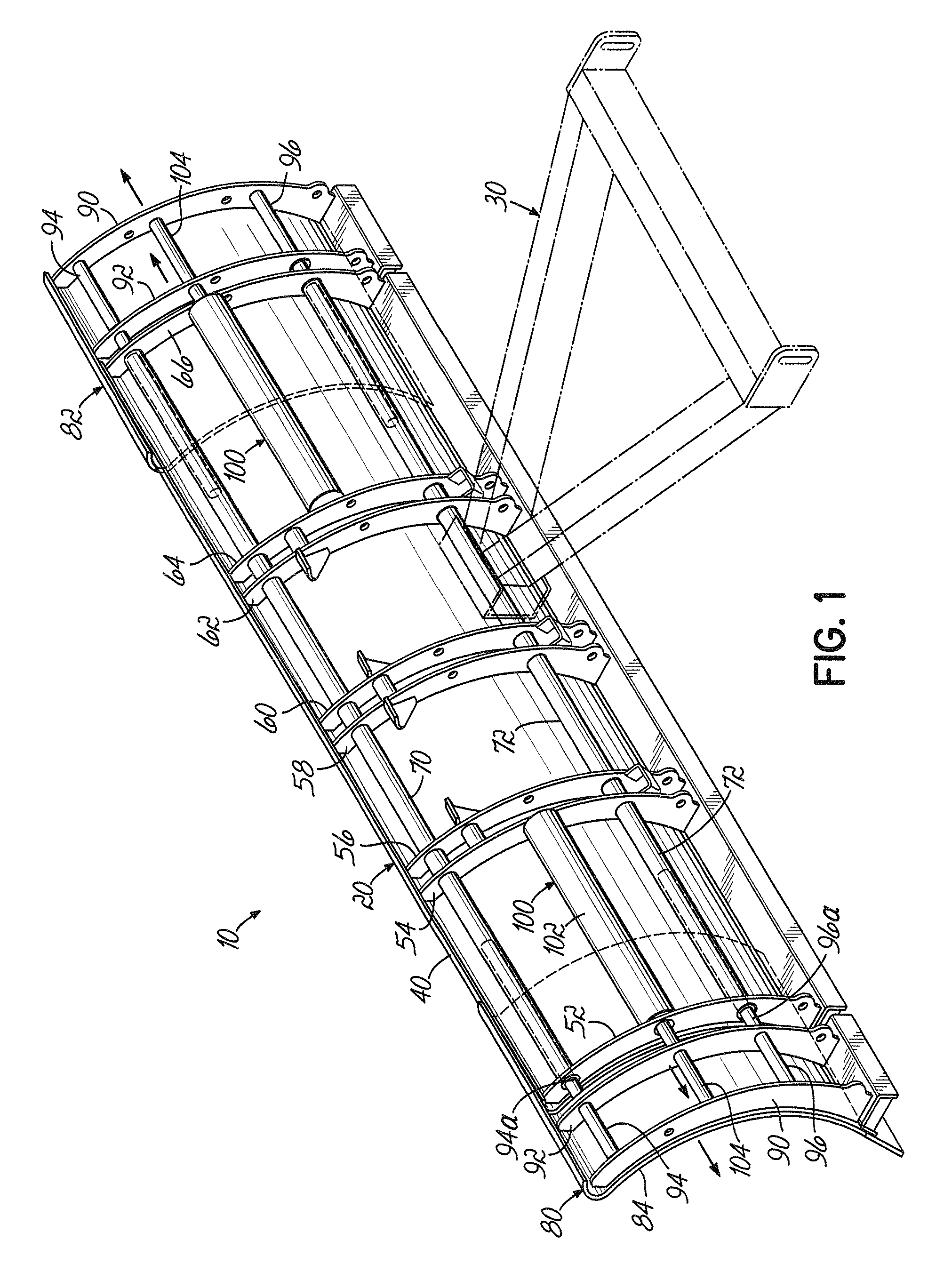
[0037]Referring first to FIG. 1, there is illustrated a plow assembly 10 according to the principles of the invention. The plow assembly 10 includes a blade assembly 20 and structure 30 (shown in phantom) attached to the blade assembly 20 and adapted to be attached to a vehicle (not shown) for mounting the blade assembly 20 to and supporting the blade assembly 20 from the vehicle.

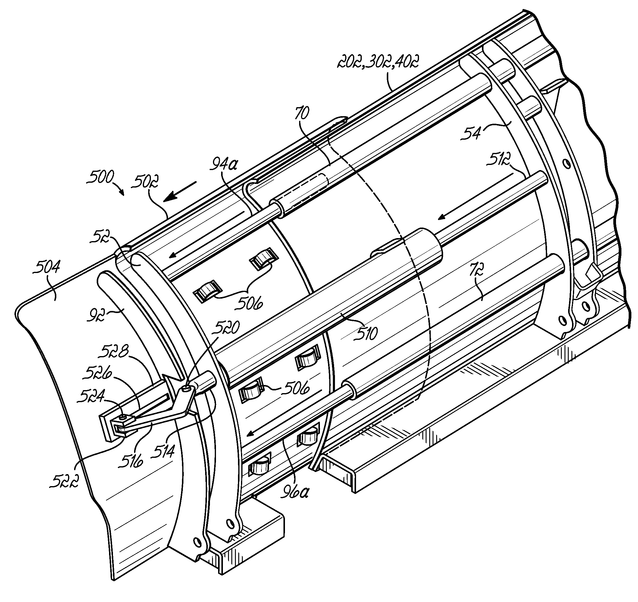
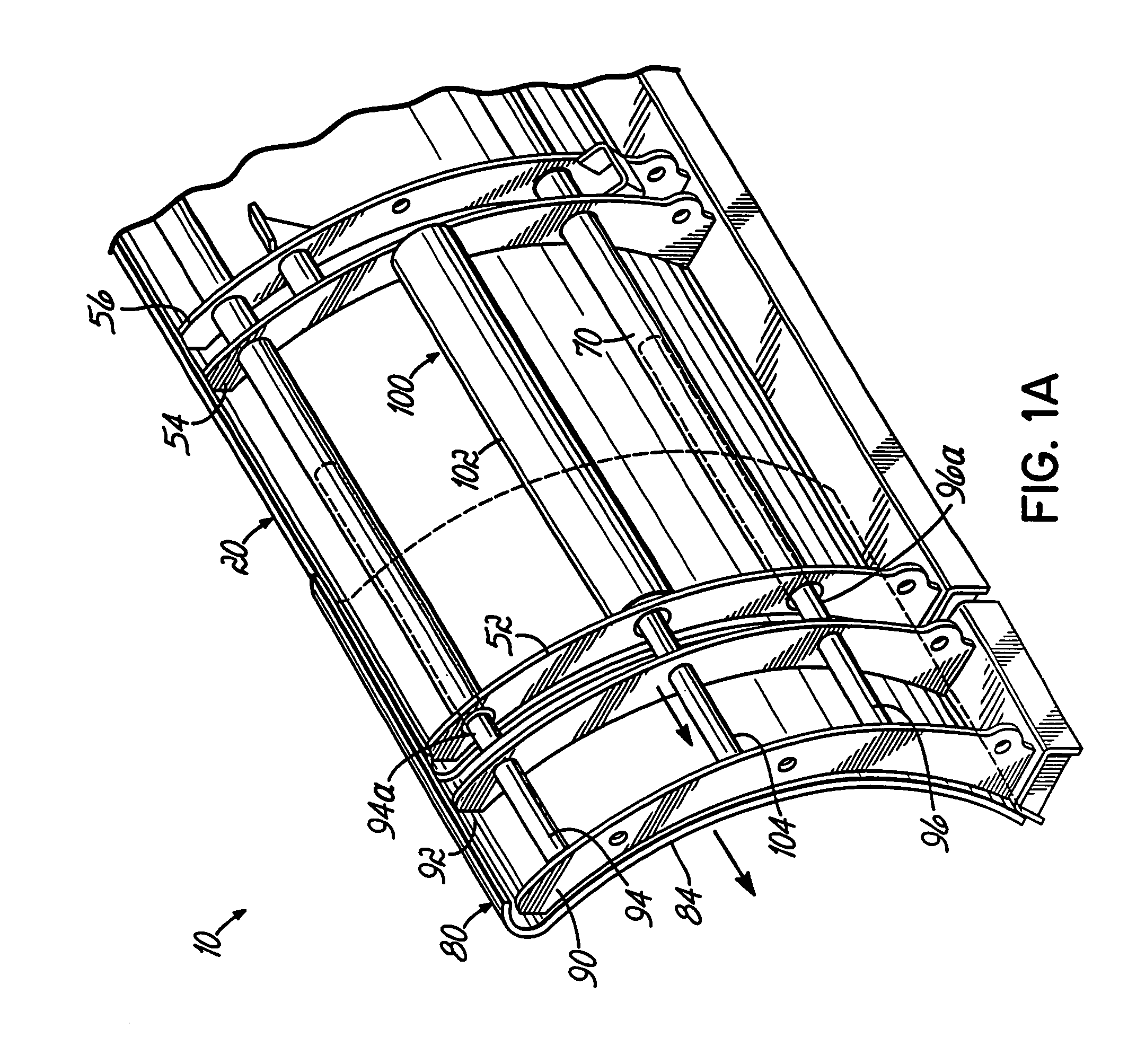
[0038]Blade assembly 20 includes a blade 40 which can have one or more stiffening ribs, for example stiffening ribs 52, 54, 56, 58, 60, 62, 64, and 66, along a rear side thereof. Blade 40 can also have one or more stiffening torque tubes, e.g., upper and lower torque tubes 70 and 72, respectively, along upper and lower edges, respectively, of the rear side of blade 40. Ribs 52, 54, 56, 58, 60, 62, 64, and 66 can be rigidly affixed to torque tubes 70 and 72 to increase the stiffness of the blade 40. At least one wing 80 is attached to at least one end of the blade 40. For example, a pair of wings can be atta...


PUM


Abstract

A plow assembly comprises a blade, structure attached to the blade and adapted to be attached to a vehicle for mounting the blade to and supporting the blade from the vehicle, and a wing attached to an end of the blade. The wing has a first portion mounted to the blade for translational movement relative thereto, and a second portion mounted to the first portion for rotational movement relative thereto. An actuator has a cylinder and first and second oppositely movable piston rods. The first piston rod and the cylinder operable to move the first portion of the wing relative to the blade, and the second piston rod and the cylinder are operable to move the second portion of the wing relative to the fist portion of the wing.

Description

RELATED APPLICATIONS[0001]This application is a continuation-in-part of application Ser. No. 11 / 256,231 filed Oct. 21, 2005, which is hereby incorporated by reference herein as if fully set forth in its entirety.FIELD OF THE INVENTION[0002]This invention relates generally to plows for moving any plowable material, and more particularly to vehicle mountable plows for moving snow and having one or more plow blade wings to aid the plow blade in moving the snow.BACKGROUND OF THE INVENTION[0003]A wide variety of plows for mounting on pickup trucks, sport utility vehicles (“SUV's”), “skid steers,” and other vehicles for moving snow is in use. Among the plows in use are straight blade plows and center hinged blade V-plows.[0004]Another type of plow in use employs rotating, translating, or rotating and translating wings mounted on the ends of the plow blade. Translating wings are useful for configuring the blade of the plow in a longer extended length for plowing, and in a shorter retracted...

Claims


Application Information

Patent Timeline
Patent Type & Authority Patents(United States)
IPC IPC(8): E01H5/06
CPCE01H5/065
Inventor WATSON, GARY E.
Owner DOUGLAS DYNAMICS
Why Eureka
Try Eureka