Adaptive and interactive scene illumination

a technology of interactive lighting and scene illumination, applied in the field of methods and equipment, can solve the problems of requiring the participation of highly skilled lighting technicians, requiring relative crude and imprecise techniques, and requiring time-consuming

Active Publication Date: 2010-03-23
THE BOEING CO
View PDF20 Cites 94 Cited by
  • Summary
  • Abstract
  • Description
  • Claims
  • Application Information

AI Technical Summary

Benefits of technology

[0008]In accordance with the exemplary embodiments described herein, adaptive, interactive lighting (“AIL”) systems are provided enabling the selective, controllable illumination of objects and areas of a field or scene, including communicating therewith, amenable to sophisticated digital image processing techniques, and which can be effected automatically and in real time.
[0014]In one particularly advantageous embodiment, the projector may spatially separate the light from the emitter into visible and NVS light by means of either a beam splitter or a dichroic filter array, and in the beam splitter embodiment, the modulated invisible portion of light may be combined with the visible portion of light by means of a beam combiner, i.e., another beam splitter operated in reverse. The camera may further comprise apparatus for detecting the NVS light either passively reflected or actively projected from portions of or objects in the illuminated scene. The projected and / or reflected NVS light, invisible to the human eye, provides a medium for the system to communicate interactively and invisibly with the scene containing systems of like kind, or selected objects within it, e.g., with NVS light reflectors disposed on selected objects in the illuminated scene, as above, thereby enabling the system to, inter alia, overcome certain instability problems of prior art adaptive headlight systems.

Problems solved by technology

While “adaptive” forms of such prior art structured lighting techniques are known, i.e., the controlled projection of light onto selected objects or portions of a scene based on feedback received from the scene, these tend to be relatively crude and imprecise techniques that require generally static scenes and frequent human intervention, and are not amenable to either the application of modern digital imaging techniques, or to being made “interactive” with objects in the illuminated scene, i.e., enabling the illuminated objects to cooperate, e.g., to communicate, actively or passively, with the lighting system, to affect the projected illumination in a desired way.
However, the procedures involved tend to be clumsy, time-consuming, and require the participation of highly skilled lighting technicians.
However, such systems suffer from a common drawback, namely, while the vehicle's headlights are dimmed, i.e., deflected downward, the driver's visibility of the road ahead is substantially impaired, particularly in low ambient lighting conditions.
While adaptive headlight systems have been proposed to overcome this problem by “projecting” a dark spot on only the frontal area of the oncoming vehicle while brightly illuminating the surrounding area, such as described in U.S. Pat. App. Pub. No. 2003 / 0137849 by R. M. Alden and U.S. Pat. No. 7,156,542 to R. Miller, et al., these suffer from a second problem recognized as inherent in such adaptive headlight systems, viz., if two approaching vehicles are each equipped with such an adaptive system, the operation of both lighting systems becomes unstable, i.e., they both oscillate between bright and dim as the vehicles approach each other.
A long-felt but as yet unsatisfied need therefore exists for adaptive, interactive lighting systems enabling the selective, controllable illumination of the objects and areas of a scene, including the establishment of one- or two-way communication with such objects and areas, amenable to sophisticated digital image processing techniques, and which can be effected automatically and in real time.

Method used


Image

  • Adaptive and interactive scene illumination
  • Adaptive and interactive scene illumination
  • Adaptive and interactive scene illumination

Examples


Embodiment Construction

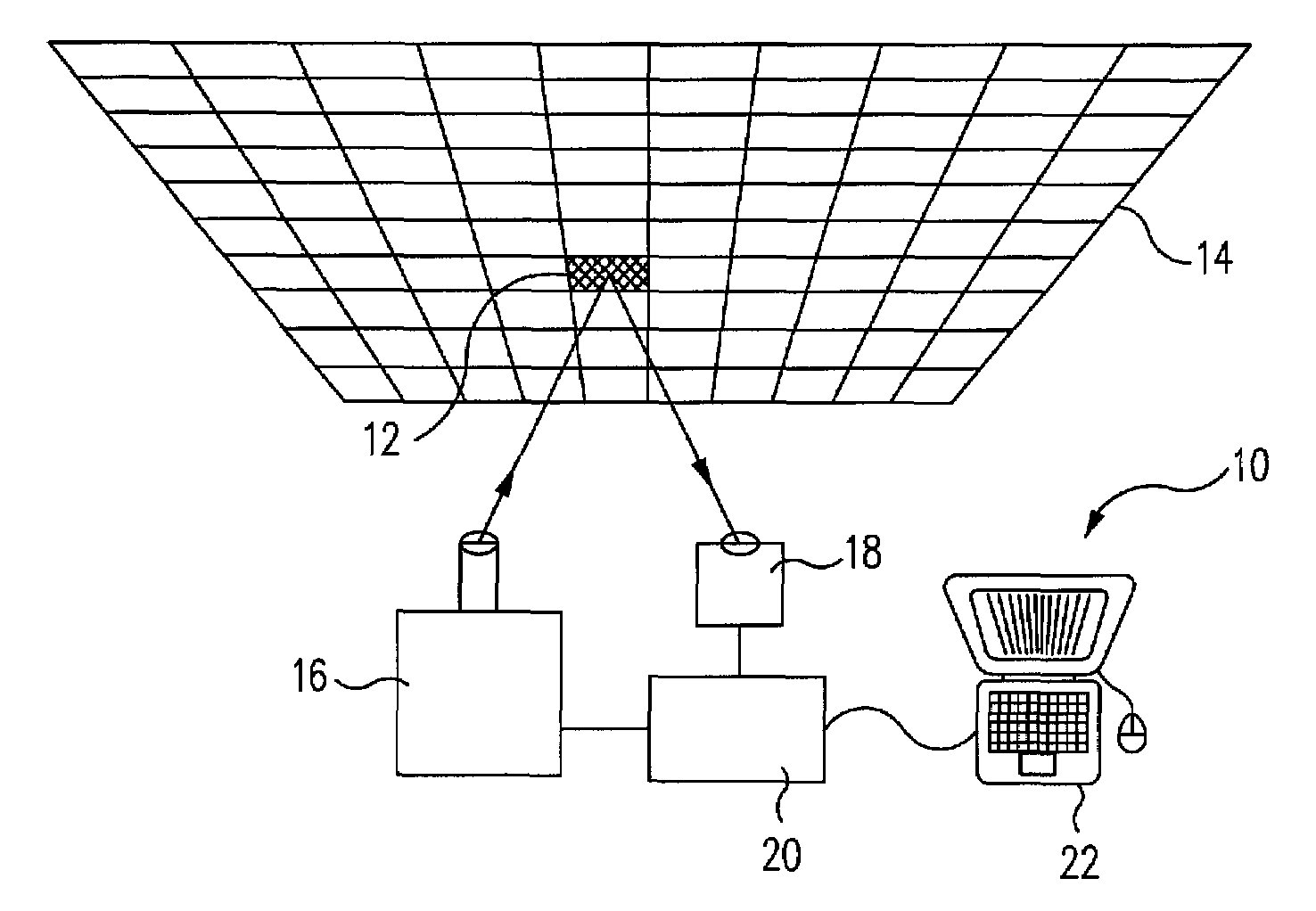
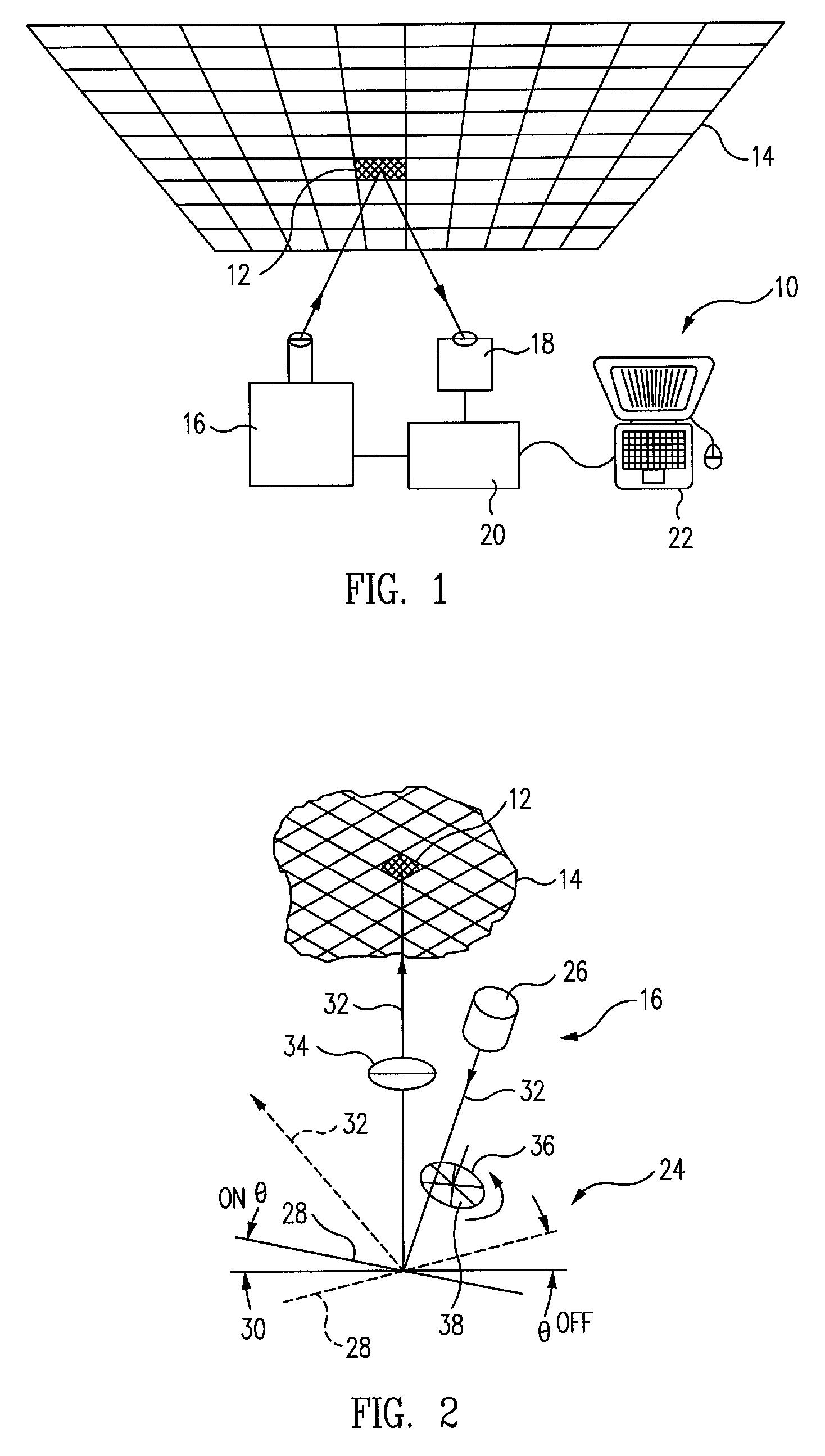
[0022]FIG. 1 is partial perspective view of an exemplary embodiment of an adaptive, interactive lighting (“AIL”) system 10 in accordance with the present invention, shown projecting light onto an individual field of view (“IFOV”) 12 of an illuminating field of regard (FOR) 14 encompassing a field or scene (not illustrated) that is to be illuminated by the system. It should be understood the illuminating FOR 14 is two-dimensional in nature, whereas, the particular field or scene onto which the FOR maps is typically three-dimensional in nature. As illustrated in the figure, the exemplary system comprises an illumination projector 16, an imaging camera 18, and an image processing electronics unit 20, including an image processor, e.g., a digital signal processor (“DSP”). Optionally, the system may also include an associated computer 22, e.g., a laptop computer, for human-interactive programming and / or control of the image processor of the system in real time, as described below.

[0023]A...


PUM


Abstract

Apparatus for adaptively and interactively lighting a scene includes a digital light projector that includes a light emitter and a digital light processor optically coupled to the emitter such that the emitter light is projected onto respective individual fields of view of a field of regard illuminating the scene in accordance with a projector control signal. A camera adjacent to the projector is operative to detect light reflected or projected from the illuminated scene and generate a signal corresponding to the detected light. A signal processor coupled to the projector and the camera is operative to receive the camera signal, process the received signal into a light projector control signal in accordance with an associated set of instructions, and apply the control signal to the light projector such that the light projected onto the respective individual fields of view of the illuminating array is controlled in accordance with the instructions.

Description

RELATED APPLICATIONS[0001]This application is a continuation-in-part of U.S. application Ser. No. 10 / 924,618, filed Aug. 23, 2004, now U.S. Pat. No. 7,227,611, issued Jun. 5, 2007, the entire disclosure of which is incorporated herein by reference.BACKGROUND[0002]This invention relates to methods and apparatus for controllably illuminating selected objects and areas of a scene in general, and in particular, to methods and apparatus for the adaptive and interactive lighting of such objects and areas, including the establishment of one- or two-way communication of information with such objects and areas.[0003]The term “structured lighting” has been applied to methods and apparatus for optical ranging, or triangulation, in which lines or other patterns of light are projected onto an object, reflected from it, and detected by a camera disposed at an angle relative to the projected light in such a way that certain three-dimensional information about the object, e.g., its shape, distance,...

Claims


Application Information

Patent Timeline
Patent Type & Authority Patents(United States)
IPC IPC(8): G03B19/18B60Q1/00
CPCB60Q1/085F21S8/003F21V14/04G03B15/02G03B21/14H05B37/0218H05B37/029B60Q2300/056F21W2131/406H04N5/7458Y02B20/46G03B17/54F21S41/675H05B47/155H05B47/11Y02B20/40
Inventor HULL, JERALD A.GALLEGOS, JONATHAN J.
Owner THE BOEING CO
Why Eureka
Try Eureka