Valve assembly for multi-channel turbine

a multi-channel turbine and valve assembly technology, applied in the direction of multiple-way valves, machines/engines, mechanical equipment, etc., can solve the problems of enhancing problems, affecting and certain temperature high enough to work efficiently, so as to increase the efficiency of the turbine

Active Publication Date: 2019-10-03
BORGWARNER INC
View PDF3 Cites 4 Cited by
  • Summary
  • Abstract
  • Description
  • Claims
  • Application Information

AI Technical Summary

Benefits of technology

[0005]Accordingly, the objective of the present in

Problems solved by technology

The individual mobility sector is experiencing a disruptive change.
However, these catalysts require a certain temperature high enough to work efficiently.
In vehicles with turbochargers this problem is enhanced because the turbocharger is usually arranged in the exhaust gas flow direction between the engine and the catalyst.
A disadvantage of known multi-channel turbines, such as dual-volute turbines or twin-s

Method used


Image

  • Valve assembly for multi-channel turbine
  • Valve assembly for multi-channel turbine
  • Valve assembly for multi-channel turbine

Examples


embodiment 1

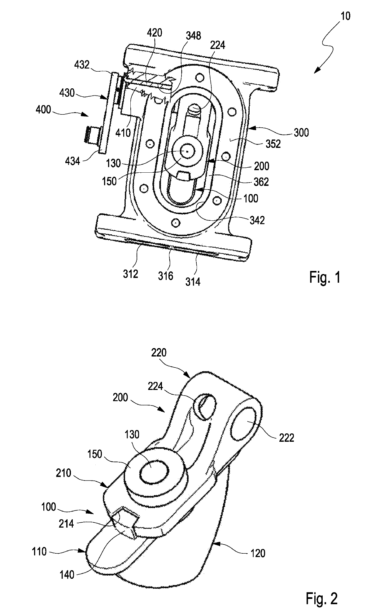
[0084]The valve assembly (10) of embodiment 1, wherein the valve body (100) further comprises a plate (110) and wherein the fin (120) protrudes from the plate (110) in a first direction.

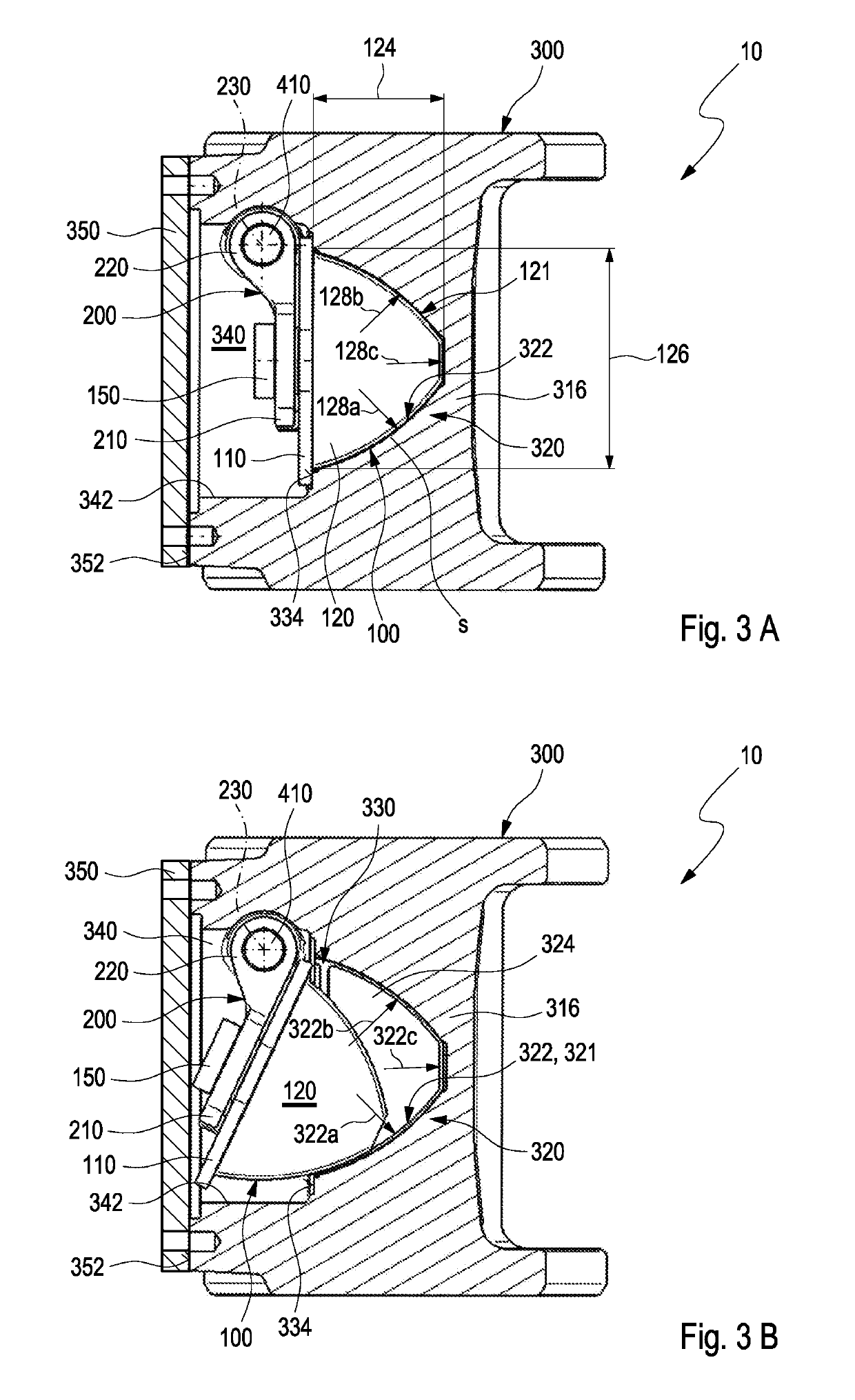
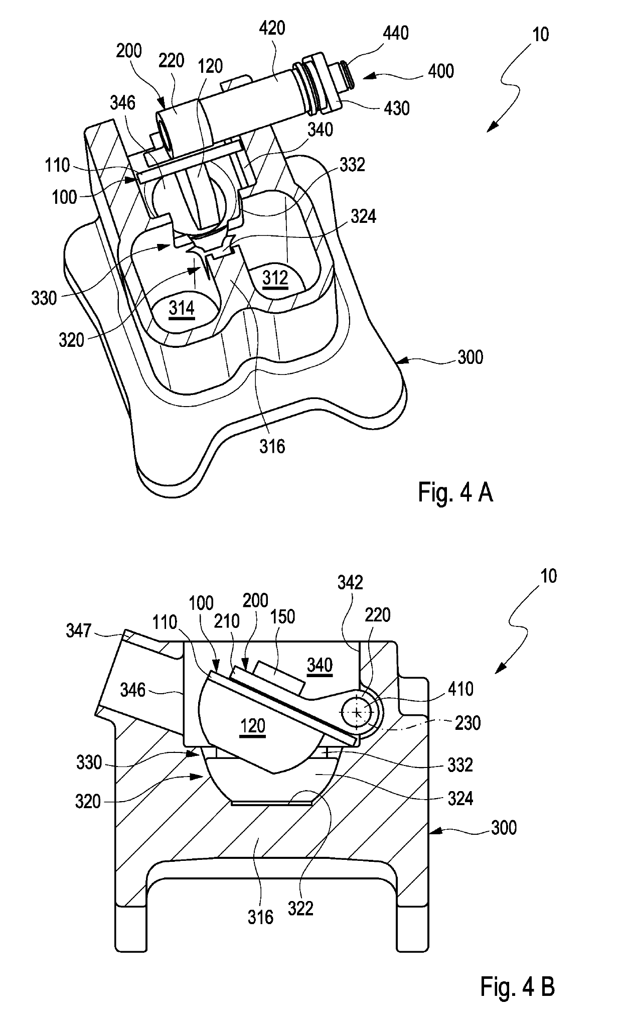
[0085]The valve assembly (10) of any one of the previous embodiments, wherein the housing portion (300) comprises a divider wall (316) separating the first volute channel (312) and the second volute channel (314), wherein the volute connecting opening (324) is arranged in the divider wall (316) defining a fin seat (322) and wherein the fin (120) interacts with the fin seat (322) to block the volute connecting opening (324) in the first position of the valve body (100).

[0086]the valve assembly (10) of any one of the previous embodiments, wherein the internal lever (200) comprises a valve portion (210) and a spindle portion (220).

embodiment 4

[0087]The valve assembly (10) of embodiment 4, wherein the internal lever (200) is coupled with the valve body (100) via the valve portion (210).

[0088]The valve assembly (10) of embodiment 5, if dependent on embodiment 2, wherein the valve body (100) further comprises a connecting portion (130) protruding from the plate (110) in a second direction opposite to the fin (120) wherein the valve portion (210) is coupled to the connecting portion (130).

embodiment 6

[0089]The valve assembly (10) of embodiment 6, wherein the valve portion (210) further comprises a connecting hole (212) and wherein the connecting portion (130) is arranged at least partly inside the connecting hole (212).

[0090]The valve assembly (10) of any one of embodiments 6 or 7, wherein the valve portion (210) is secured to the connecting portion (130) via a washer (150).

[0091]The valve assembly (10) of any one of embodiments 4 to 8, wherein the valve body (100) comprises a stop (140) and wherein the valve portion (210) comprises an orientation recess (214) which is engaged with the stop (140) to rotationally secure the internal lever (200) with respect to the valve body (100).

[0092]The valve assembly (10) of any one of embodiments 4 to 9, further comprising a lever assembly (400) with a spindle (410), wherein the internal lever (200) is coupled with the spindle (410) in the cavity (340) via the spindle portion (210).


PUM


Abstract

The disclosure relates to a valve assembly 10 for controlling a volute connecting opening 324 of a multi-channel turbine 500. The valve assembly 10 comprises a housing portion 300, a valve body 100 and an internal lever 200. The housing portion 300 defines a first volute channel 312, a second volute channel 314 and a volute connecting region 320. The housing portion 300 further comprises a cavity 340. The cavity 340 is separated from the volutes 312, 314 and can be accessed from outside the housing portion 300 via a housing opening 342 which extends from outside the housing portion 300 into the cavity 340. The volute connection region 320 is located between the first volute channel 312 and the second volute channel 314 and defines a volute connecting opening 324. The valve body 100 is inserted in the cavity 340 of the housing portion 300 and comprises at least one fin 120. The internal lever 200 is coupled with the valve body 100 and configured to pivotably move the valve body 100 between a first position and a second position. In the first position of the valve body 100, the fin 120 blocks the volute connecting opening 324.

Description

CROSS-REFERENCE TO RELATED APPLICATIONS[0001]The present application claims priority to and all the benefits of European Patent Application No. 19158717.9 filed Feb. 22, 2019, and German Patent Application No. 202018101705.5 filed on Mar. 27, 2018, which are hereby expressly incorporated herein by reference in their entirety.TECHNICAL FIELD[0002]This disclosure relates to a valve assembly for controlling a volute connecting opening of a multi-channel turbine. Furthermore, the invention relates to a multi-channel turbine and a charging apparatus having such a valve assembly. A method for mounting such a valve assembly is also provided.BACKGROUND[0003]The individual mobility sector is experiencing a disruptive change. Especially, the increasing number of electric vehicles entering the market and stricter emission regulations of legislators demand higher efficiencies from traditional internal combustion engine ICE vehicles. Therefore, more and more vehicles are equipped with efficiency...

Claims


Application Information

Patent Timeline
IPC IPC(8): F02B37/18F01D17/14
CPCF05D2220/40F02B37/186F01D17/146F01D17/105F01D25/24F02B37/183F02C9/18F02B37/025F02B37/22F16K1/2021F16K1/2014F16K1/205F16K1/2064Y02T10/12F01D17/145F16K11/072F05D2240/14F02B37/18
Inventor WALKINGSHAW, JASON ROBERTCEMPIREK, ONDREJINJAC, IVAN
Owner BORGWARNER INC
Why Eureka
Try Eureka