Base station system for mobile communication

a mobile communication and base station technology, applied in the field of mobile communication systems, can solve the problems of high cost of relevant units as well as optical lines or coaxial cables, difficult and costly installation of such cables, and high cost of the entire base system in terms of installation, maintenance and managemen

Active Publication Date: 2010-03-23
SAMSUNG ELECTRONICS CO LTD
View PDF33 Cites 21 Cited by
  • Summary
  • Abstract
  • Description
  • Claims
  • Application Information

AI Technical Summary

Benefits of technology

[0007]Therefore, the present invention has been made in view of the above problems, and it is an object of the present invention to provide a base station system for mobile communication, enabling transmission of a high quality of signal between a base station and a remote RF unit (RRU), through a line which can be installed cheaply and easily, the remote RF unit being installed remotely from the base station, the remote RF unit transceiving an RF (radio frequency) signal with a mobile terminal.
[0008]It is another object of the present invention to provide a base station system for mobile communication, which is able to flexibly extend a wireless channel capacity as well as coverage.

Problems solved by technology

However, in using such repeater systems, high costs of relevant units as well as optical lines or coaxial cables, and difficult and costly installation thereof are shortcomings.
As a result, an entire base system requires high costs in terms of installation, maintenance and management.
In addition, since conventional repeater systems perform a function of extending only the coverage, it is impossible to extend wireless channel capacities using such conventional repeater systems.

Method used


Image

  • Base station system for mobile communication
  • Base station system for mobile communication
  • Base station system for mobile communication

Examples


Embodiment Construction

[0018]Now, preferred embodiments of the present invention will be described in detail with reference to the annexed drawings. In the following description, a detailed description of known functions and configurations incorporated herein will be omitted when it may make the subject matter of the present invention rather unclear.

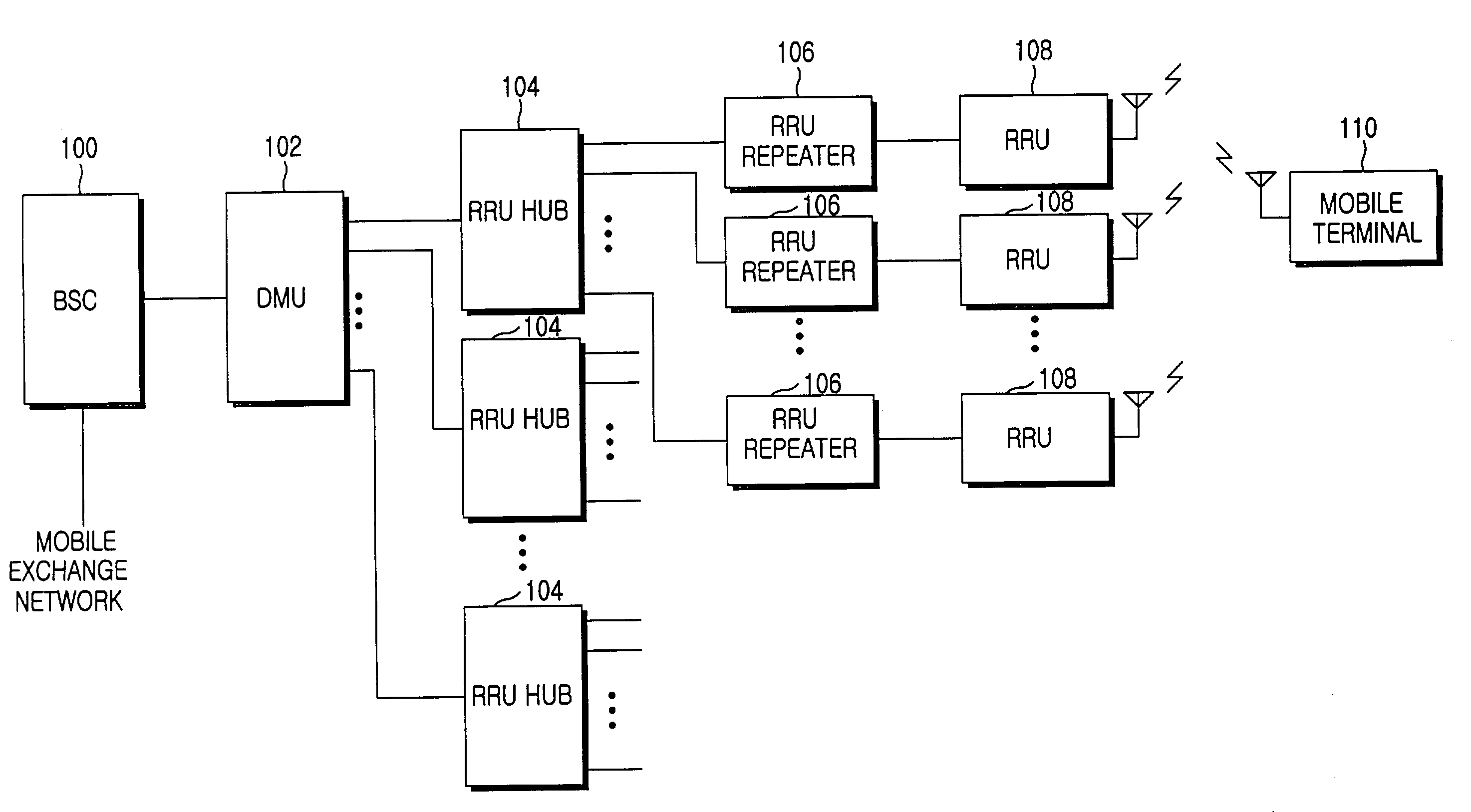
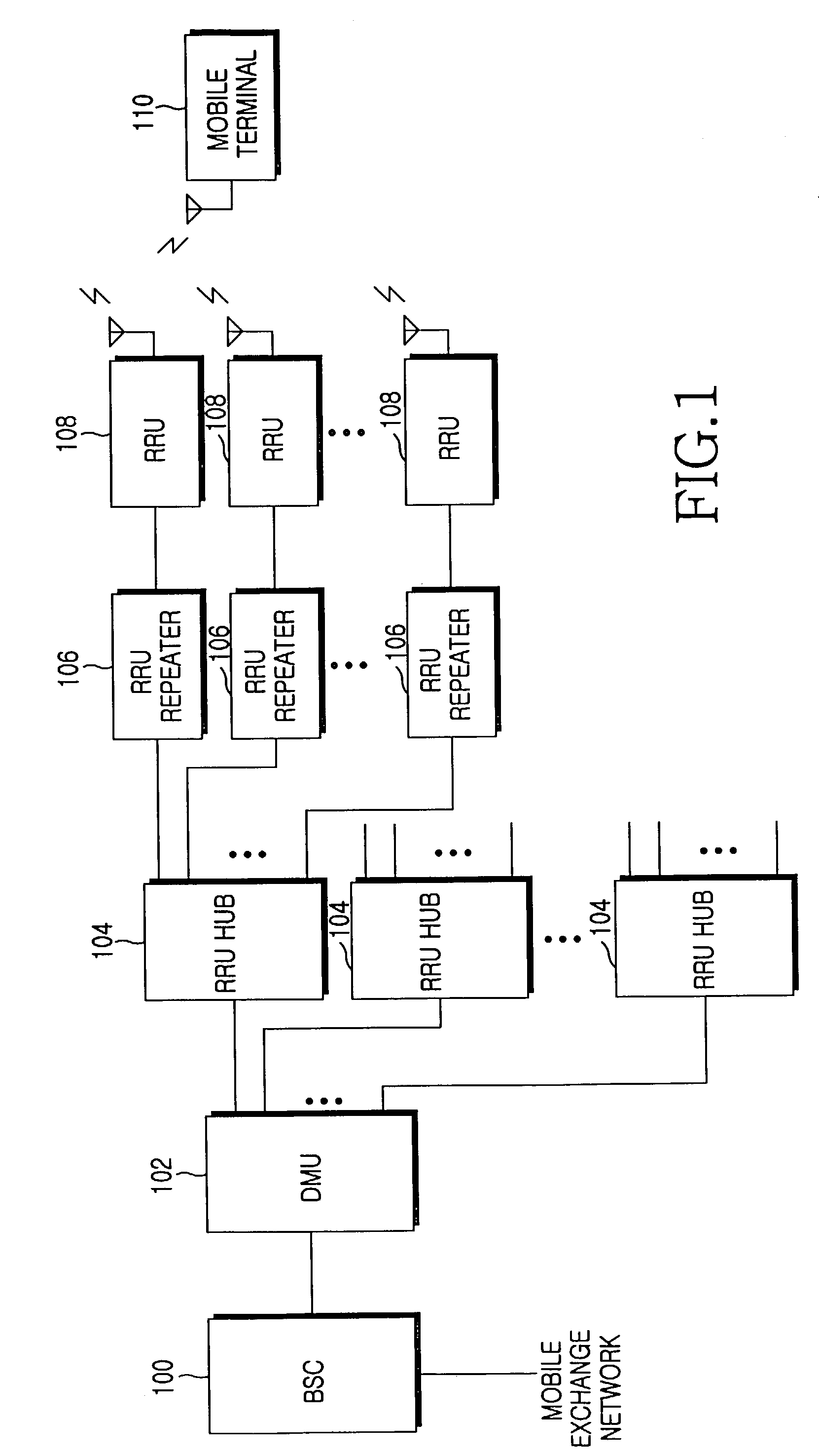
[0019]FIG. 1 is a block diagram showing a configuration of a base station system for mobile communication in accordance with the invention. A typical base station controller 100, which is connected to a mobile exchange network, is connected with a digital modem unit 102, while the digital modem unit 102 is connected with a plurality of remote RF unit hubs 104 via an Ethernet using a twisted pair cable. Each of the plurality of remote RF unit hubs 104 is connected with a plurality of remote RF units 108, which transceive an RF signal with a mobile terminal 110, through corresponding remote RF unit repeaters 106, among a plurality of remote RF unit repeaters 106...


PUM


Abstract

A base station system for mobile communication between a mobile terminal and a base station controller, the base station system utilizing a digital modem unit for receiving a signal to be transmitted to the mobile terminal from the base station controller, framing the received signal according to a frame format for transmission different than an Ethernet specified data format, the frame format being a predetermined remote RF (radio frequency) unit frame, the digital modem unit transmitting a plurality of the remote RF unit frames in series over an Ethernet using twisted pair cable, at least one remote RF unit hub receiving the remote RF unit frames transmitted by the digital modem unit and distributing the received remote RF unit frames to a plurality of remote RF units via the Ethernet using twisted pair cable, and the plurality of remote RF units producing a deframed signal by deframing the remote RF unit frames received from the remote RF unit hub, modulating the deframed signal to an RF signal, and transmitting the RF signal to the mobile terminal, wherein the remote RF unit frames are divided into a traffic frame for use in transmitting traffic data, which is transmitted and received by the mobile terminal and a control frame for use in transmitting a control address and control data, the control address differentiating the plurality of remote RF units from one another, the control data containing a command to control operation and functions of the plurality of remote RF units.

Description

CLAIM OF PRIORITY[0001]This application makes reference to, incorporates the same herein, and claims all benefits accruing under 35 U.S.C. §119 from an application entitled BASE STATION SYSTEM FOR MOBILE COMMUNICATION earlier filed in the Korean Industrial Property Office on 2 Jul. 2002, and there duly assigned Serial No. 2002-37915 by that Office.BACKGROUND OF THE INVENTION[0002]1. Field of the Invention[0003]The present invention relates to a system for mobile communication, and more particularly to a base station system for mobile communication.[0004]2. Description of the Related Art[0005]Typically, a cellular system for mobile communication comprises a plurality of mobile terminals for transmitting and receiving users' signals, a base station part, the Base Transceiver Station (BTS) for relaying the transmission and reception signal of the plurality of mobile terminals via an appropriate process, a base station controlling part, the Base Station Controller (BSC) for controlling ...

Claims


Application Information

Patent Timeline
Patent Type & Authority Patents(United States)
IPC IPC(8): H04J3/16H04J3/22H04B1/38H04J3/24H04M1/00H04L12/44H04W88/08H04W92/00H04W92/12
CPCH04W88/085H04W92/12
Inventor KIM, KI-CHULBAIK, SUNG-JUN
Owner SAMSUNG ELECTRONICS CO LTD
Why Eureka
Try Eureka