Receivers for television signals

a television signal and receiver technology, applied in the field of television signal receivers, can solve the problems of unsatisfactory requirements for establishing a link with the hdr via a telephone network, increasing the possibility of clashing the programme schedule, and not recording desired programmes, so as to reduce the time shift and reduce the time shift

Active Publication Date: 2010-03-23
SKY CP LTD
View PDF65 Cites 15 Cited by
  • Summary
  • Abstract
  • Description
  • Claims
  • Application Information

AI Technical Summary

Benefits of technology

[0012]According to another aspect of the invention there is provided a receiver for receiving signals representative of a television programme, and for outputting simultaneously a signal representative of the television programme shifted in time, the receiver comprising a recorder for recording data representative of the television programme, and for playing back data representative of the time-shifted television programme, wherein the receiver is operable to output signals representative of the television programme at an increased frame rate so as to reduce the time shift.
[0013]Preferably, the receiver may comprise a first data buffer for buffering data representative of the television programme to be recorded by the recorder; a second data buffer for buffering data being played back from the recorder; and a processor for selectively causing data to be transferred from the first data buffer to the recorder at a first data rate or from the recorder to the second data buffer at a second data rate, wherein the second data rate is higher than the first data rate to cause the receiver to output signals representative of the television programme at the increased frame rate so as to reduce the time shift. The first data rate is in accordance with the bandwidth of received signals, and the second data rate is in accordance with a user-selected frame rate.

Problems solved by technology

The requirement to establish a link with the HDR via a telephone network is undesirable.
This is because the HDR may not always “on line” for reasons such as costs, or because the telephone connection is to be used otherwise.
If a user relies on the programme schedule information when programming his HDR to record a desired programme, he may unknowingly rely on out-of-date programme schedule data, which in turn may result in the desired programme not being recorded.
Also, due to the ever increasing variety of television channels and programmes, it is getting more likely that there will be a clash in the programme schedule of television programmes which the user would wish to record.
Currently known video cassette recorders (VCRs) and HDRs fail to address this problem.
In addition, some parts of a recorded television programme may not be of interest to the viewer.
Also, when watching a series of recorded video clips, the user may not be interested in some of the clips but can only jump forward to the next clip of interest by fast-forwarding the video tape.
This clearly is inconvenient.
To record parts of programmes in which the viewer is not interested, in any case, is a waste of hard disk storage capacity.
Since this is not a very exact science, it may be that in certain environments the broadcast advertisements do not appeal to the viewers at all, or do at least not use the full potential of the advertisement breaks.
The prior art has not addressed this problem.

Method used


Image

  • Receivers for television signals
  • Receivers for television signals
  • Receivers for television signals

Examples


Embodiment Construction

1. System Overview

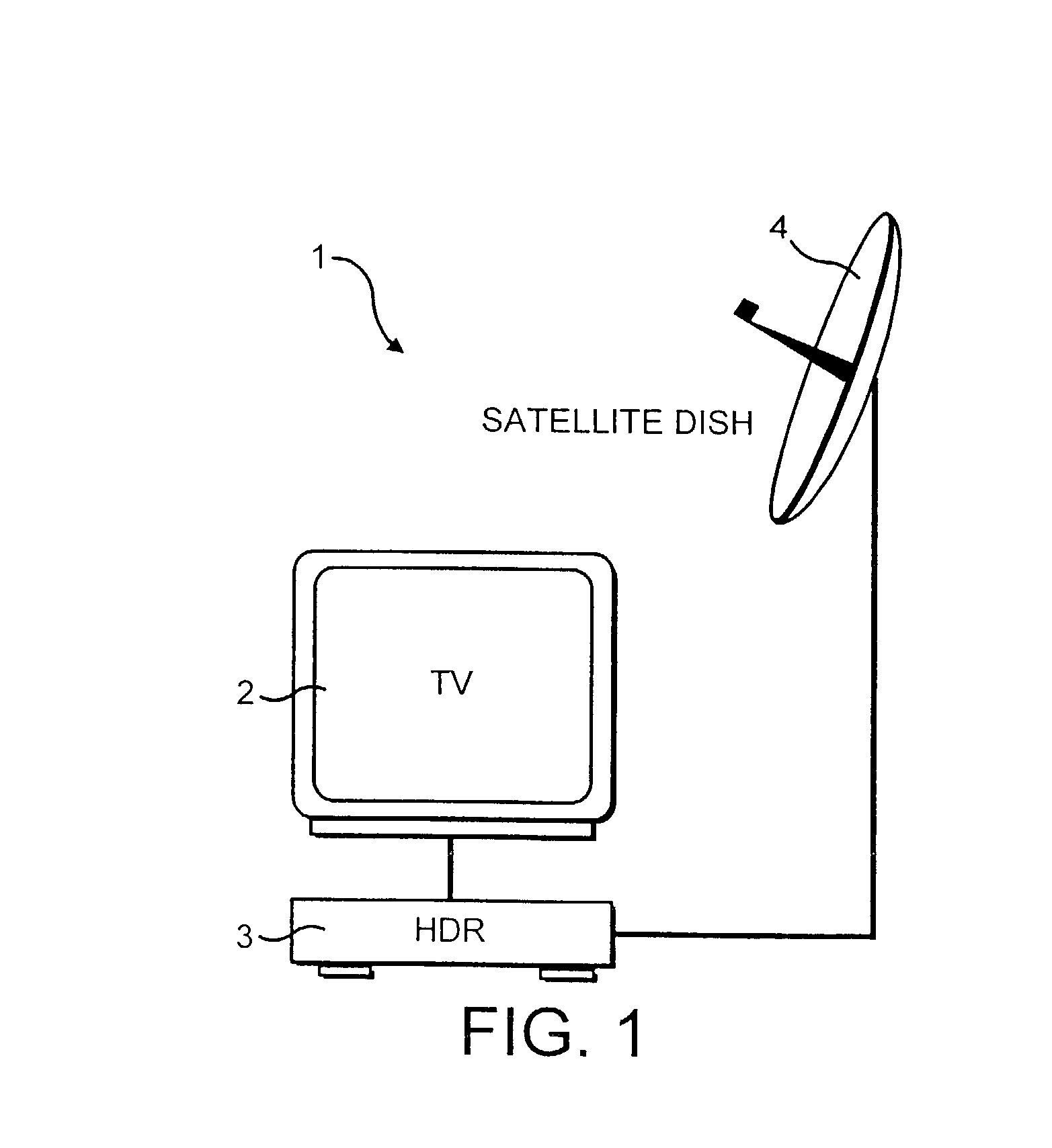
[0033]Referring now to FIG. 1 of the accompanying drawings, a television system 1 comprises a television 2 (TV), a hard disk recorder 3 (HDR), and a satellite dish 4. The HDR 3 comprises a satellite receiver which is connected to the satellite dish 4 for reception of signals from a satellite (not shown). The HDR receives signals from the satellite dish 4, including television signals, in a plurality of channels.

2. Hard Disk Recorder (HDR)—Overview

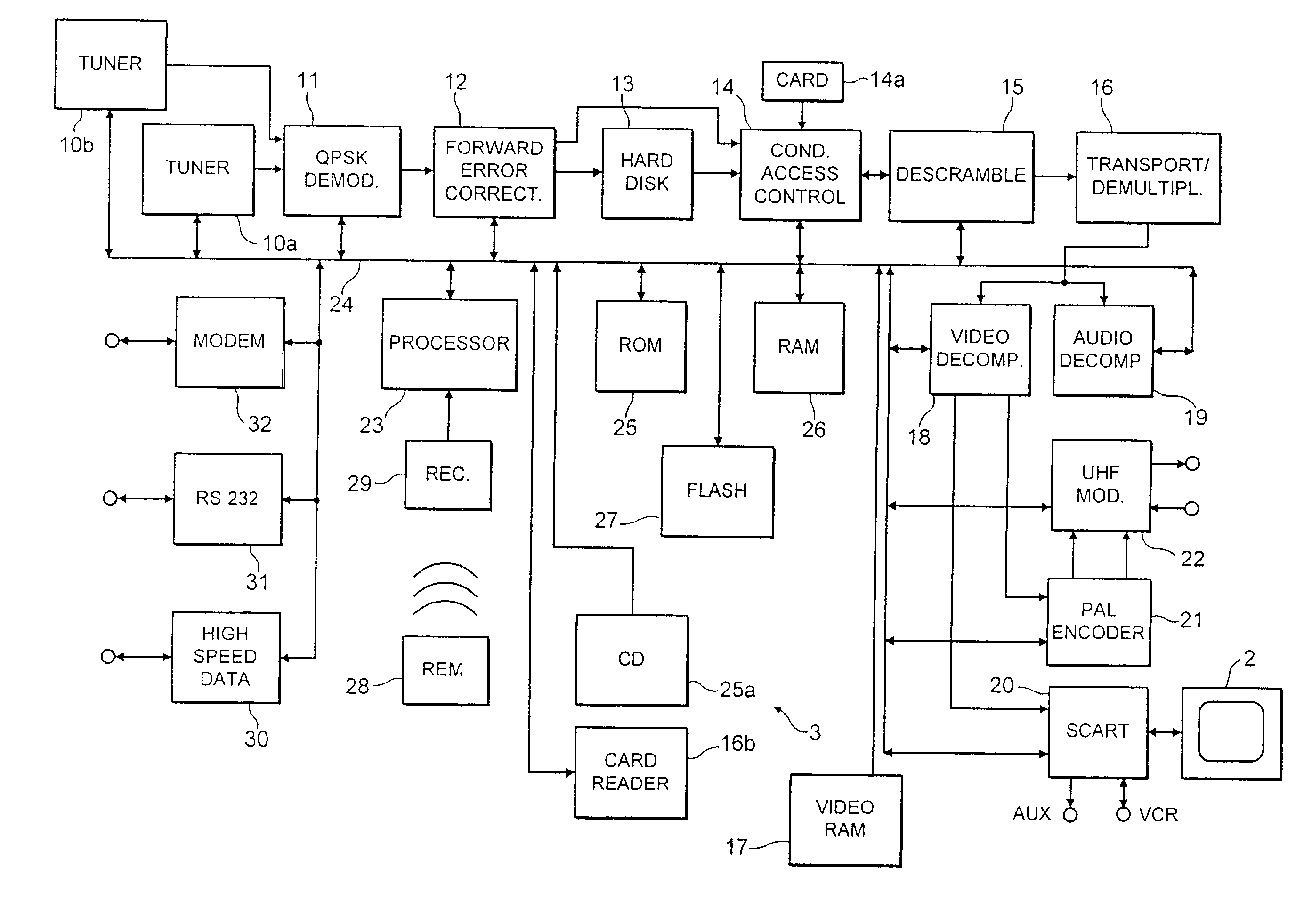
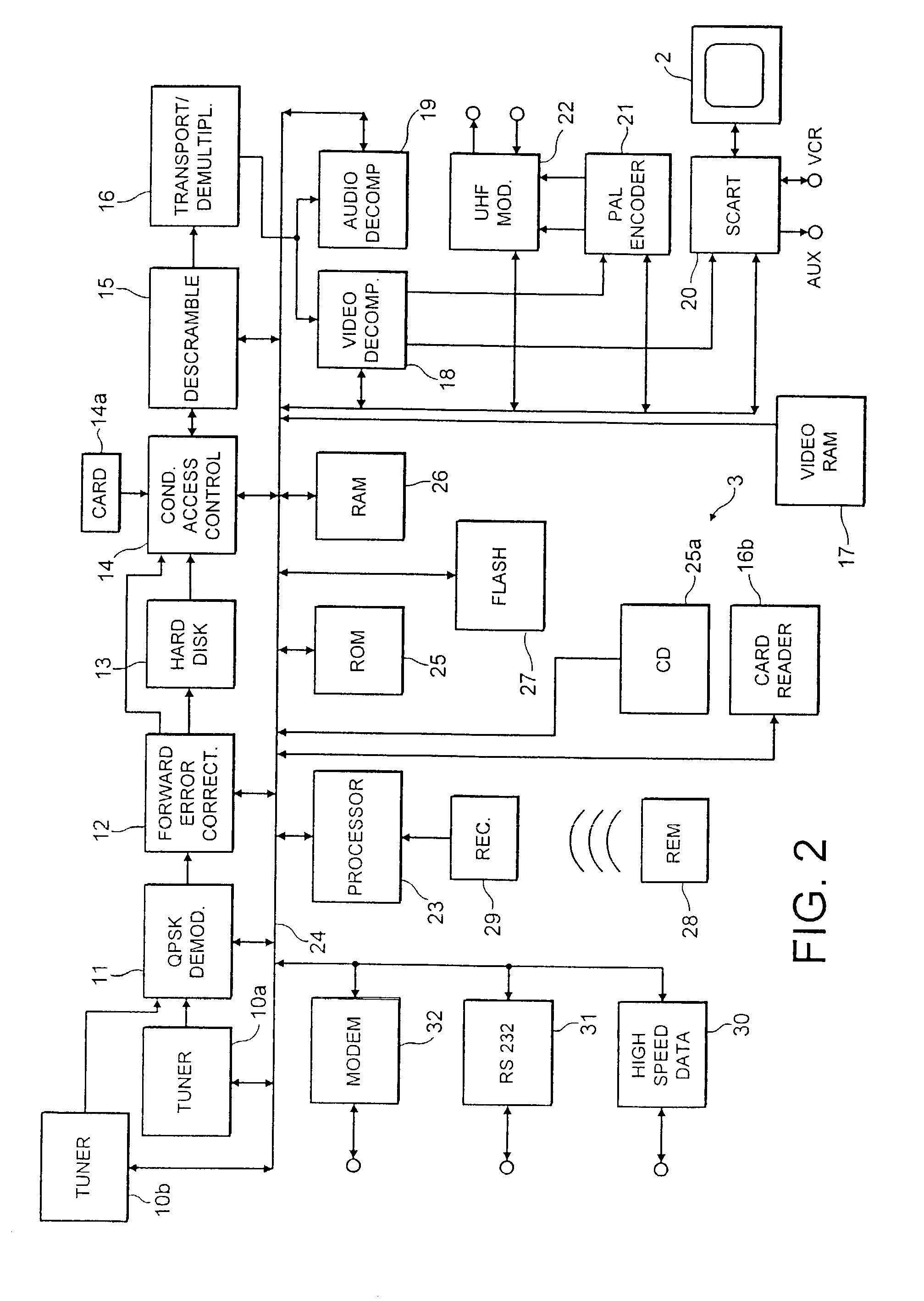
[0034]FIG. 2 of the accompanying drawings shows the HDR 3 in greater detail. Signals from the dish antenna 4 (shown in FIG. 1) are input to first and second tuners 10a and 10b and from there to a quadrature phase shift key (QPSK) demodulator 11. The first and second tuners 10a and 10b are tunable into the same or different channels for simultaneous reception of the same or different television programmes. Demodulated signals are error-corrected by way of a forward error corrector circuit 12. The HDR 3 comprises a hard disk...


PUM


Abstract

A Hard Disk Recorder (HDR) (3) is arranged to receive signals signals defining television programmes and television programme schedule data. The HDR receives updated programme schedule data substantially constantly in a dedicated programme schedule data channel. The HDR is arranged to output the programme schedule data for display on a television screen (2). The HDR comprises a hard disk (16) for recording received television programmes. A remote control (28) is provided to select television programmes to be recorded from the displayed programme schedule. Furthermore, the HDR is arranged to receive additional programme schedule information included in each of the received television channels which information is used to control the hard disk to record pre-programmed television programmes according to schedule. The hard disk is operable to record simultaneously two different television programmes received in different channels. Also, the HDR is operable to replay a currently broadcast programme offset in time. The time offset can be overcome by playing back the part of the programme inside the time offset at an increased frame rate. Furthermore, the HDR is arranged to receive transition signals indicating transitions between parts of programmes, such as transitions between advertisements and the “actual” programmes. The HDR is operable to use these transition signals, for example, to skip between transitions in previously recorded programmes replayed from the hard disk.

Description

CROSS REFERENCE TO RELATED APPLICATIONS[0001]The present application is a national stage filing under 35 U.S.C. § 371 of International Application No. PCT / GB00 / 03065, filed 9 Aug. 2000, and claims priority under 35 U.S.C. §119 to Great Britain patent application No. 9918772, filed 9 Aug. 1999 and Great Britain patent application No. 0001326.8, filed 20 Jan. 2000.[0002]The inventions relates to improvements in receivers for television signals.BACKGROUND OF THE INVENTION[0003]A Hard Disk Recorder (HDR) is known which comprises a television receiver and a hard disk for recording received television programmes. The HDR is arranged to be connected to the telephone network in order to receive through the telephone network television programme schedule information for display on a television screen. A telephone link must be established with the provider of the programme schedule data every time the programme schedule data is to be updated. Such updating may be performed at regular interval...

Claims


Application Information

Patent Timeline
Patent Type & Authority Patents(United States)
IPC IPC(8): H04N7/26H04N5/765H04B1/16H04N5/00H04N5/445H04N5/76H04N5/775H04N5/781H04N5/782H04N5/85H04N7/16H04N7/24H04N9/804
CPCH04N5/44543H04N21/8456H04N5/782H04N5/783H04N5/85H04N21/235H04N21/4147H04N21/4263H04N21/42661H04N21/4314H04N21/4325H04N21/4333H04N21/4334H04N21/435H04N21/44016H04N21/440281H04N21/443H04N21/4508H04N21/4542H04N21/458H04N21/47214H04N21/482H04N21/4821H04N21/485H04N21/812H04N21/84H04N21/8455H04N5/76H04N5/765H04N5/775H04N5/7755H04N5/781H04N9/8042H04N21/47
Inventor BODKIN, NIGELWILLAME, XAVIERCROSSLEY, ROBINJAMES, NICK
Owner SKY CP LTD
Why Eureka
Try Eureka