Industrial robot

a robot and industrial technology, applied in the field of industrial robots, can solve the problems of large motor torque, complicated design, limited accuracy, etc., and achieve the effects of fast and accurate manipulation of objects, increased operating/unused operating volume ratio, and high accuracy

Inactive Publication Date: 2010-03-30
ABB (SCHWEIZ) AG
View PDF12 Cites 8 Cited by
  • Summary
  • Abstract
  • Description
  • Claims
  • Application Information

AI Technical Summary

Benefits of technology

[0015]The object of the invention is to provide a rapid PKM, defined above, that offers high accuracy, stiffness and an increased operating / unused operating volume ratio. A second object of the invention is to provide a method for a fast and accurate manipulation of an object. A third object of the invention is to use a robot according to the first aspect and a method according to the second aspect for high accuracy operations.
[0019]The parallel kinematic manipulator comprises at least three independent supporting first arm parts, each connected to a second arm part. The second arm parts together comprise in total 6 links with only axial forces and are arranged, as described above, to connect the platforms, optimizing the overall accuracy and stiffness of the manipulator.
[0020]The at least three first arm parts of the parallel kinematic manipulator according to the invention are arranged with the possibility of endless rotation about one or several axes. Thus, the endless rotation of the PKM reduces the unused operating volume to one or several different cylindrical volumes around respective axis of rotation and the unused operating volume is decreased. Another consequence of this design is that the minimum and maximum radial operating distance between the movable platform and respective axis of rotation is increased and consequently, the operating volume is increased. A reduced unused operating volume and an increased operating volume results according to the invention in an increased operating / unused operating volume ratio.
[0021]The robot according to the invention has a desirable dynamic character due to even dynamic force distribution and to lack of undesirable torsion and bending forces in the design. This results in high speed, acceleration and accuracy of the robot.
[0022]In one embodiment of the invention, the supporting first arm parts are arranged to rotate around one of at least two parallel axes. Each first arm part is arranged connected to the stationary platform and is actuated by a separate actuating means. Furthermore, actuating means is arranged to actuate only one single supporting arm part each and not actuating any part of the stationary platform or any other actuator. Therefore, the design of the robot according to the invention has a decreased moving mass compared to prior art robots. It is possible to have low effect as well as low mass of the actuators actuating the arms. This minimizes the moment of inertia and maximizes the acceleration and speed capability of the robot at an available torque level. This design is free from sources of undesirable play. The result according to the invention is a robot design with low mechanical natural frequencies and transmission errors and therefore possessing a minimum moment of inertia and even distribution of the same and furthermore a design free from undesirable stresses. This results in a robot, in accordance with the invention, having high accuracy and desirable dynamic performance.

Problems solved by technology

According to the statements above, a serial kinematic robot comprises a large mass and thus becomes compliant with low mechanical natural frequencies, the accuracy is limited and large motor torques are required for accomplishing high acceleration, jerk and speed movements possible.
This makes the design more complicated and the manipulator relatively expensive to process.
Another consequence is that the first driving means carries the highest moment of inertia and there will be an uneven distribution of the moment of inertia in the manipulator.
Moreover, the mechanical natural frequencies will be lower because of the extra mass that axis 2 has to rotate, which gives a less accurate control at higher motion frequencies.
The result is a relatively bulky design of a manipulator with a limited operating volume.
Moreover, the shown manipulator comprises less stiffness, lower accuracy and much lower mechanical natural frequencies when compared with a manipulator comprising arm parts transmitting only compressive and tensile forces.
Prior art includes a manipulator, which has a voluminous and expensive design with a limited operating volume (FIG. 16 in the prior art).
For certain robot applications, it is important due to enormously high initial costs to make a PKM with a small unused operating volume in relation to the operating volume and which can work close to each other.
The known industrial robots comprising a parallel kinematic manipulator do not satisfy this need.

Method used


Image

  • Industrial robot
  • Industrial robot
  • Industrial robot

Examples


Embodiment Construction

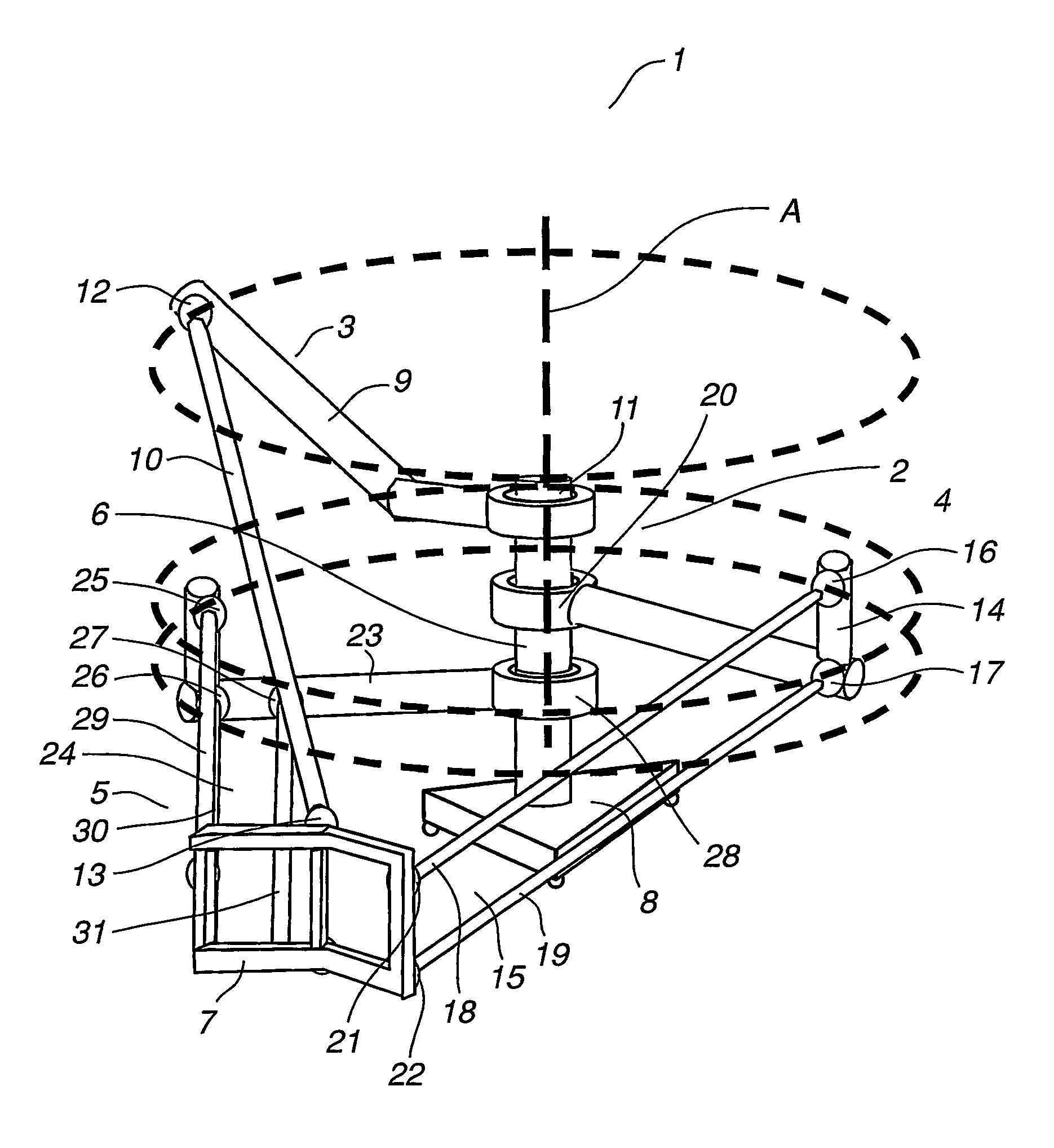
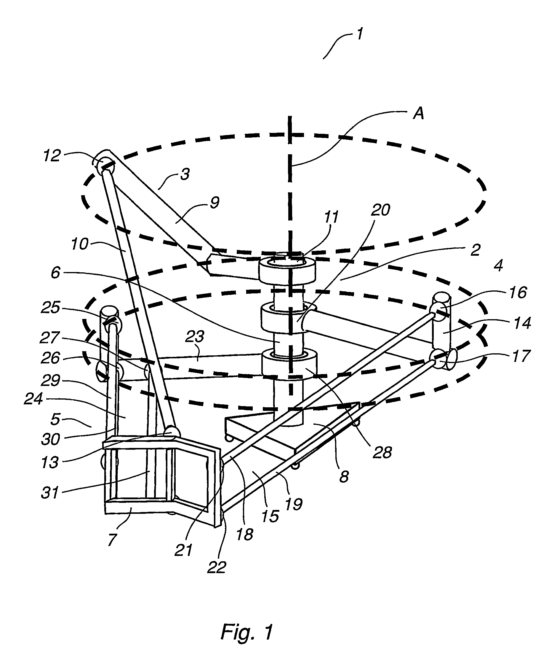
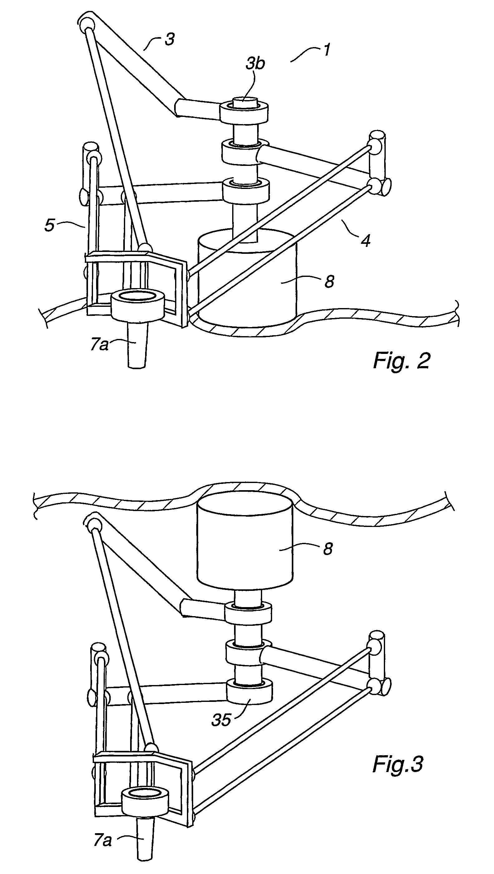
[0055]FIG. 1 is an industrial robot 1 comprising a manipulator 2 with three arms 3, 4, 5 arranged rotating around a common axis A. The arms 3, 4, 5 are connecting a stationary column 6a and a movable platform 7 in the combination 3 / 2 / 1 for carrying an object 7a (FIG. 2) to be manipulated. The column 6a is supported by a detachable stand 8, which is fixed to the ground.

[0056]The first arm 3 comprises a supporting first arm part 9 and a second arm part comprising a link arrangement 10 pivotally connected in series via a joint 12. The supporting first arm part 9 is rotationally attached to the column 6 through connecting means 11. The link arrangement 10 is pivotally connected to the movable platform 7 via a joint 13.

[0057]The second arm 4 comprises a supporting first arm part 14 and a second arm part comprising a link arrangement 15 pivotally connected in series via joints 16 and 17. The supporting first arm part 14 is rotationally attached to the column 6a through connecting means 20...


PUM


Abstract

An industrial robot including a parallel kinematic manipulator of an object in space. The manipulator includes a stationary platform, a movable platform for carrying the object, and at least three arms connecting the platforms. Each arm includes a first arm part connected to the stationary platform for manipulating the movable platform.

Description

CROSS-REFERENCE TO RELATED APPLICATIONS[0001]This application claims priority to Swedish patent application 0200343-2 filed 6 Feb. 2002 and is the national phase under 35 U.S.C. § 371 of PCT / SE03 / 00200.TECHNICAL FIELD[0002]The present invention relates to an industrial robot, including a manipulator and a control unit having means for automatically operating the manipulator. The manipulator comprises a parallel kinematic manipulator including at least three arms, each comprising a link arrangement. The three link arrangements together carry, directly or indirectly, a working platform member arranged to execute the function aimed at.[0003]The determination “parallel kinematic manipulator”, PKM, is defined as a manipulator comprising a first stationary element, a second movable element (platform) and at least three arms. Each arm comprises a supporting first arm part and a second arm part, the latter consisting of a link arrangement connected to the movable platform. Each first arm pa...

Claims


Application Information

Patent Timeline
Patent Type & Authority Patents(United States)
IPC IPC(8): B25J17/00B66C1/00B25J11/00B25J9/10B25J17/02
CPCB25J9/107B25J17/0266Y10T74/20335Y10T74/20305
Inventor KOCK, SONKEOESTERLEIN, ROLANDBROGARDH, TORGNY
Owner ABB (SCHWEIZ) AG
Why Eureka
Try Eureka