
Dual mode vehicle exhaust system and associated method

a dual-mode, exhaust system technology, applied in the direction of machines/engines, mechanical equipment, transportation and packaging, etc., can solve the problems of not enabling a user to determine what type of sound,

Inactive Publication Date: 2010-03-30
QUAGLIA FERNANDO
View PDF7 Cites 19 Cited by
  • Summary
  • Abstract
  • Description
  • Claims
  • Application Information

AI Technical Summary

Benefits of technology

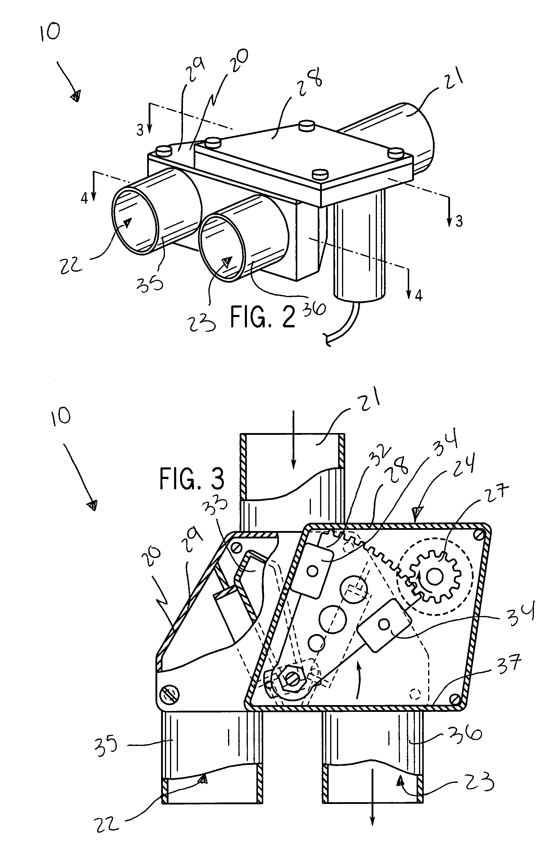
[0016]The first arm has a corrugated proximal edge directly interlocked with the toothed gear in such a manner that the first and second arms effectively articulate along counter clockwise and clockwise directions when the toothed gear rotates along clockwise and counter clockwise directions respectively. The first arm includes a plurality of stop members directly attached to longitudinal sides thereof. Such stop members terminate laterally of the longitudinal sides and are engageable with oppositely faced inner walls of the upper chamber to thereby prevent the first arm from traveling beyond predetermined threshold positions defined within the upper chamber.

Problems solved by technology

Unfortunately, this prior art example does not enable a user to determine what type of sound is emitted from a vehicle exhaust system.

Method used


Image

  • Dual mode vehicle exhaust system and associated method
  • Dual mode vehicle exhaust system and associated method
  • Dual mode vehicle exhaust system and associated method

Examples


Embodiment Construction

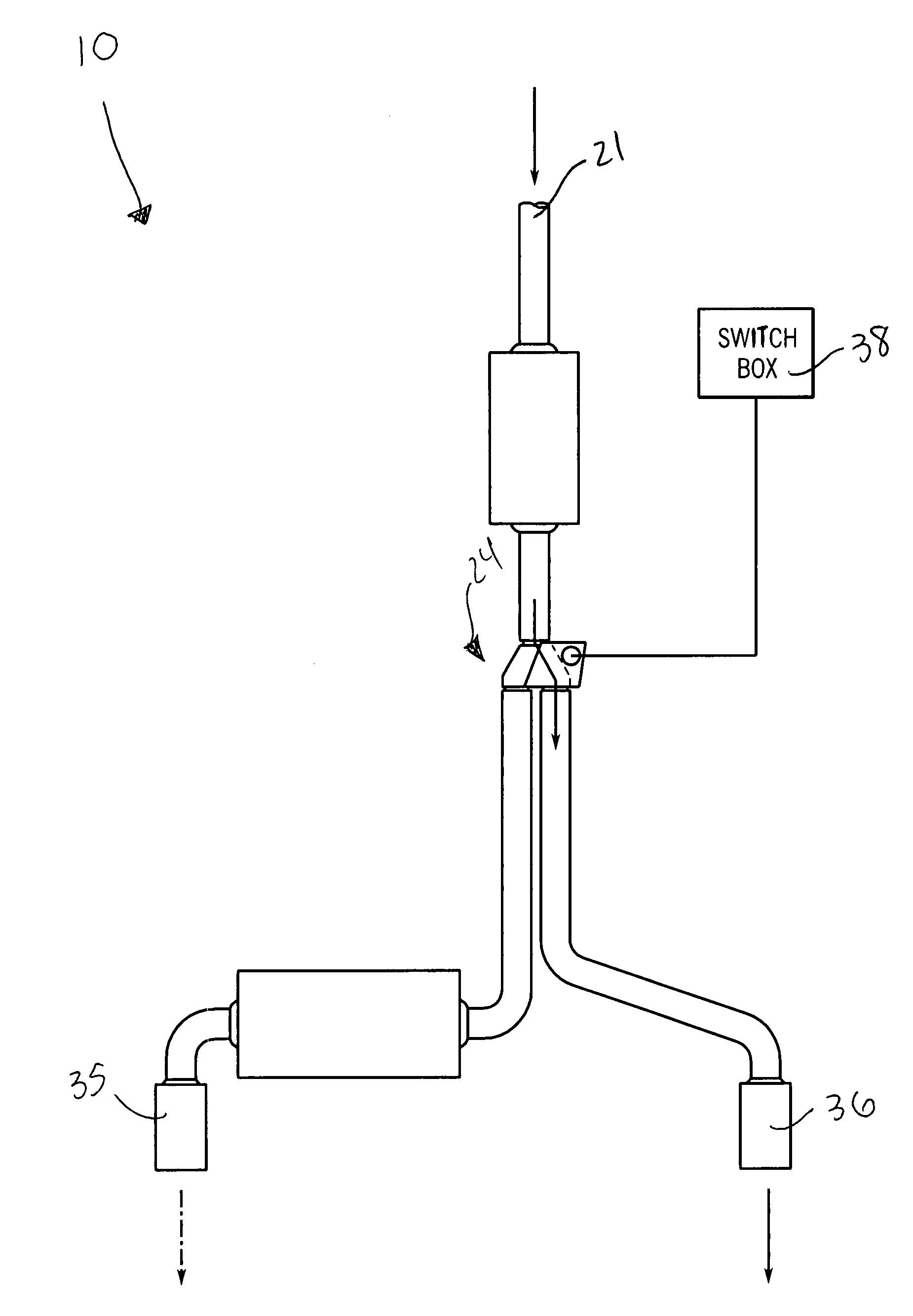
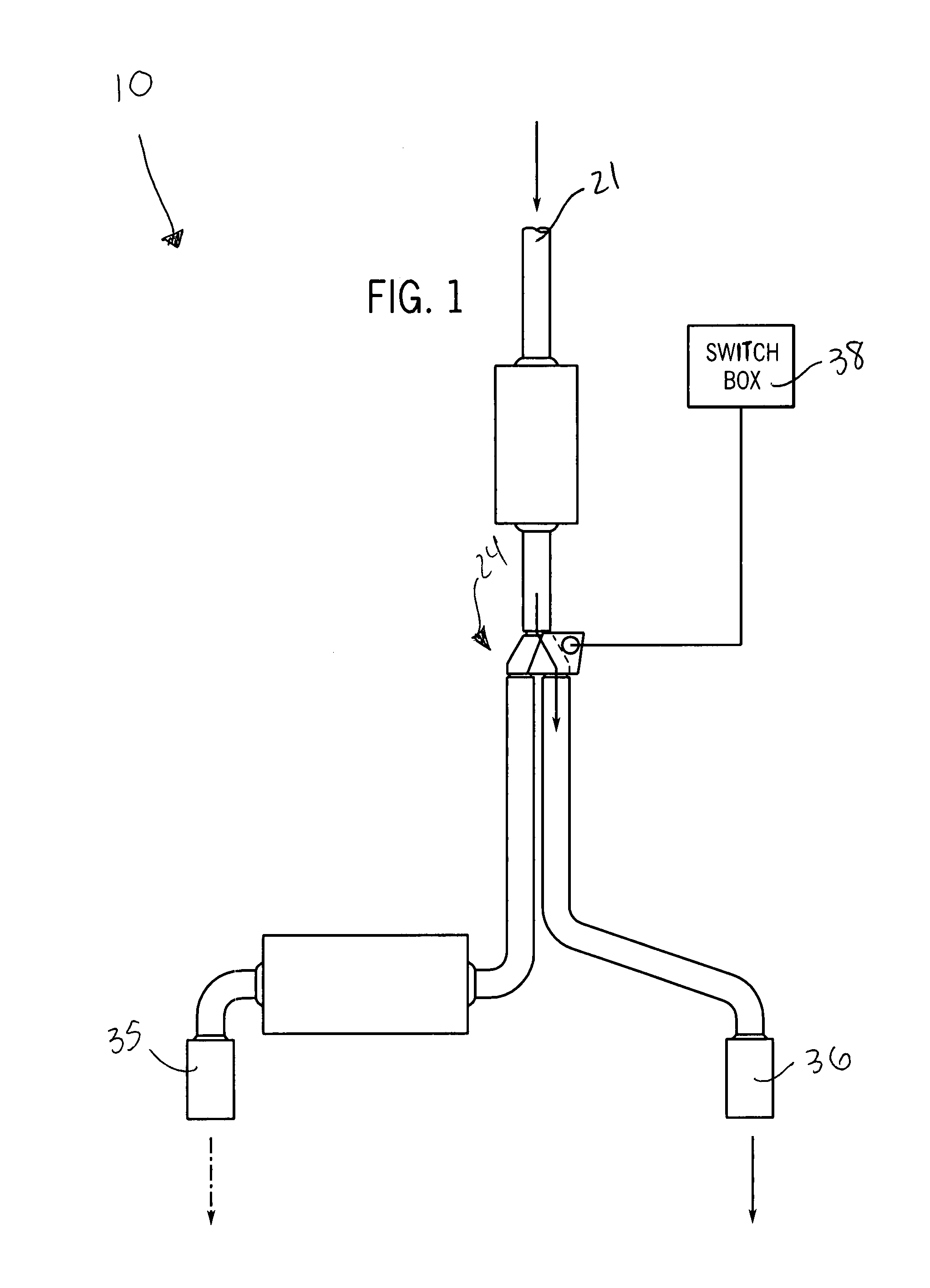
[0029]The present invention will now be described more fully hereinafter with reference to the accompanying drawings, in which a preferred embodiment of the invention is shown. This invention may, however, be embodied in many different forms and should not be construed as limited to the embodiment set forth herein. Rather, this embodiment is provided so that this application will be thorough and complete, and will fully convey the true scope of the invention to those skilled in the art. Like numbers refer to like elements throughout the figures.

[0030]The apparatus of this invention is referred to generally in FIGS. 1-6 by the reference numeral 10 and is intended to protect a dual-mode exhaust system. It should be understood that the apparatus 10 may be used with many different types of vehicles and should not be limited in use with only those vehicles mentioned herein.

[0031]Referring to FIGS. 1, 2, 3, 4, 5 and 6, a dual-mode exhaust system 10 includes a housing 20 with an input port...


PUM


Abstract

A dual-mode exhaust system includes a housing with an input port attached to the existing muffler exhaust system and positioned downstream thereof. The system further includes a mechanism for selectively distributing vehicle exhaust from the input port to the first and second output ports, upper and lower chambers vertically stacked within the housing, and first and second vertically spaced pendulum arms disposed within the upper and lower chambers respectively and anchored at respective distal ends thereof respectively. First and second vehicle exhaust pipes are coupled to the first and second output ports.

Description

CROSS REFERENCE TO RELATED APPLICATIONS[0001]This application claims the benefit of U.S. Provisional Application No. 60 / 823,019, filed Aug. 21, 2006, the entire disclosures of which are incorporated herein by reference.STATEMENT REGARDING FEDERALLY SPONSORED RESEARCH OR DEVELOPMENT[0002]Not Applicable.REFERENCE TO A MICROFICHE APPENDIX[0003]Not Applicable.BACKGROUND OF THE INVENTION[0004]1. Technical Field[0005]This invention relates to exhaust systems and, more particularly, to a dual mode vehicle exhaust system for allowing a user to generate a desired audible sound from an existing muffler exhaust system of the vehicle.[0006]2. Prior Art[0007]There was a time when America's auto makers competed to offer consumers the biggest tail fins, the most powerful engines, the latest in bucket seats and vinyl roofs. Many car models, referred to as muscle cars, produced a distinctive engine sound that conveyed a sense of power waiting to be unleashed. Today, however, emphasis is placed on pr...

Claims


Application Information

Patent Timeline
Patent Type & Authority Patents(United States)
IPC IPC(8): F01N1/18
CPCF01N13/087F01N2390/02F01N2410/00
Inventor QUAGLIA, FERNANDO
Owner QUAGLIA FERNANDO
Learn More