
Auxiliary steering system for vehicles

a technology of auxiliary steering and vehicles, which is applied in the direction of steering initiation, vessel construction, instruments, etc., can solve the problems of difficulty in encountering, high cost, and the risk of striking the cars parked fore and aft of the limited space, and achieve the effect of displacing the associated

Active Publication Date: 2008-12-30
EPHRAIM UBON B
View PDF32 Cites 7 Cited by
  • Summary
  • Abstract
  • Description
  • Claims
  • Application Information

AI Technical Summary

Benefits of technology

[0011]The auxiliary vehicle steering system includes a user interface for receiving a user input and transmitting a control output signal associated with the user input signal. Such a user interface is conveniently located within the vehicle, allowing for easy access thereto and quick activation of the system.
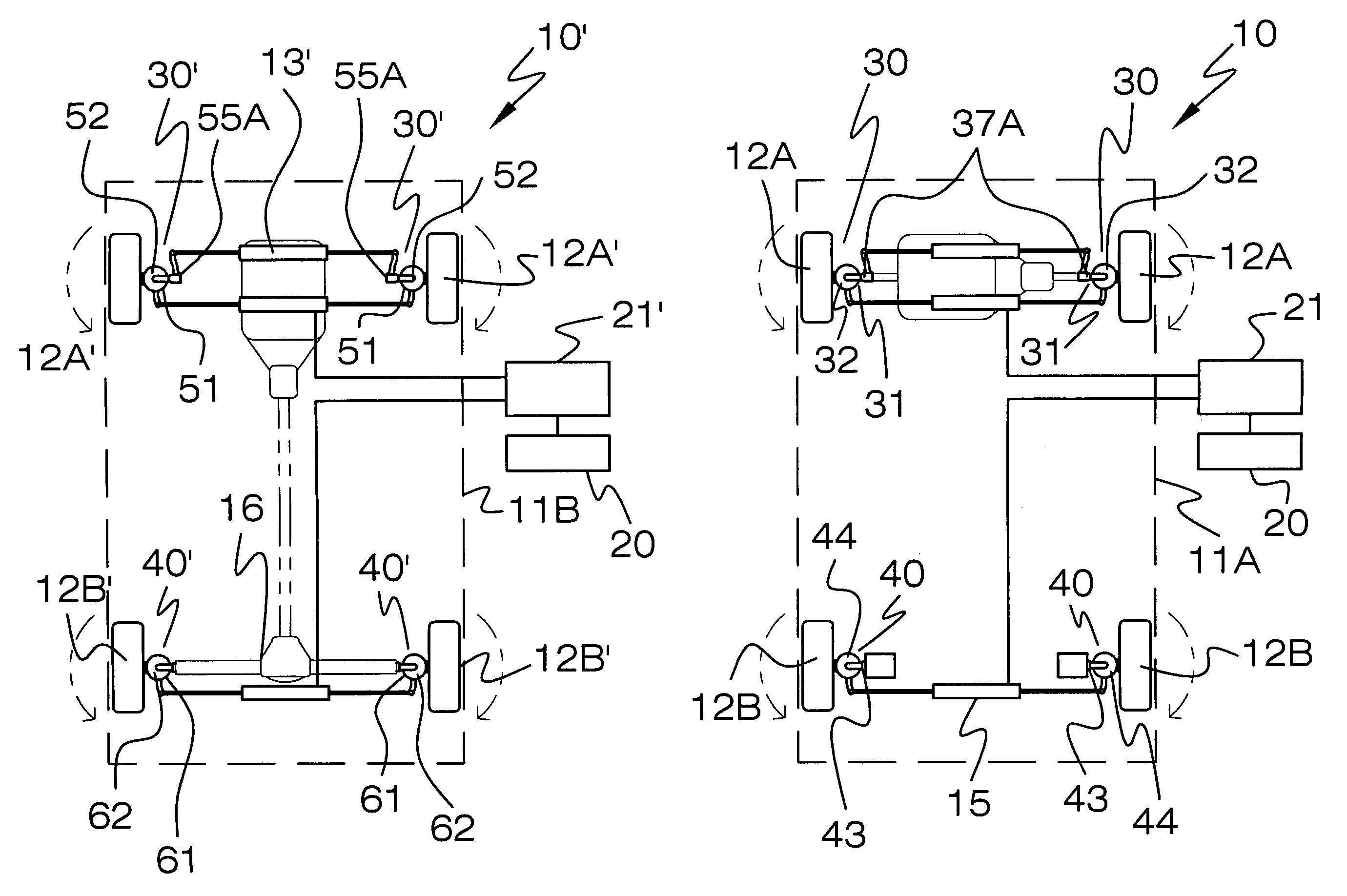
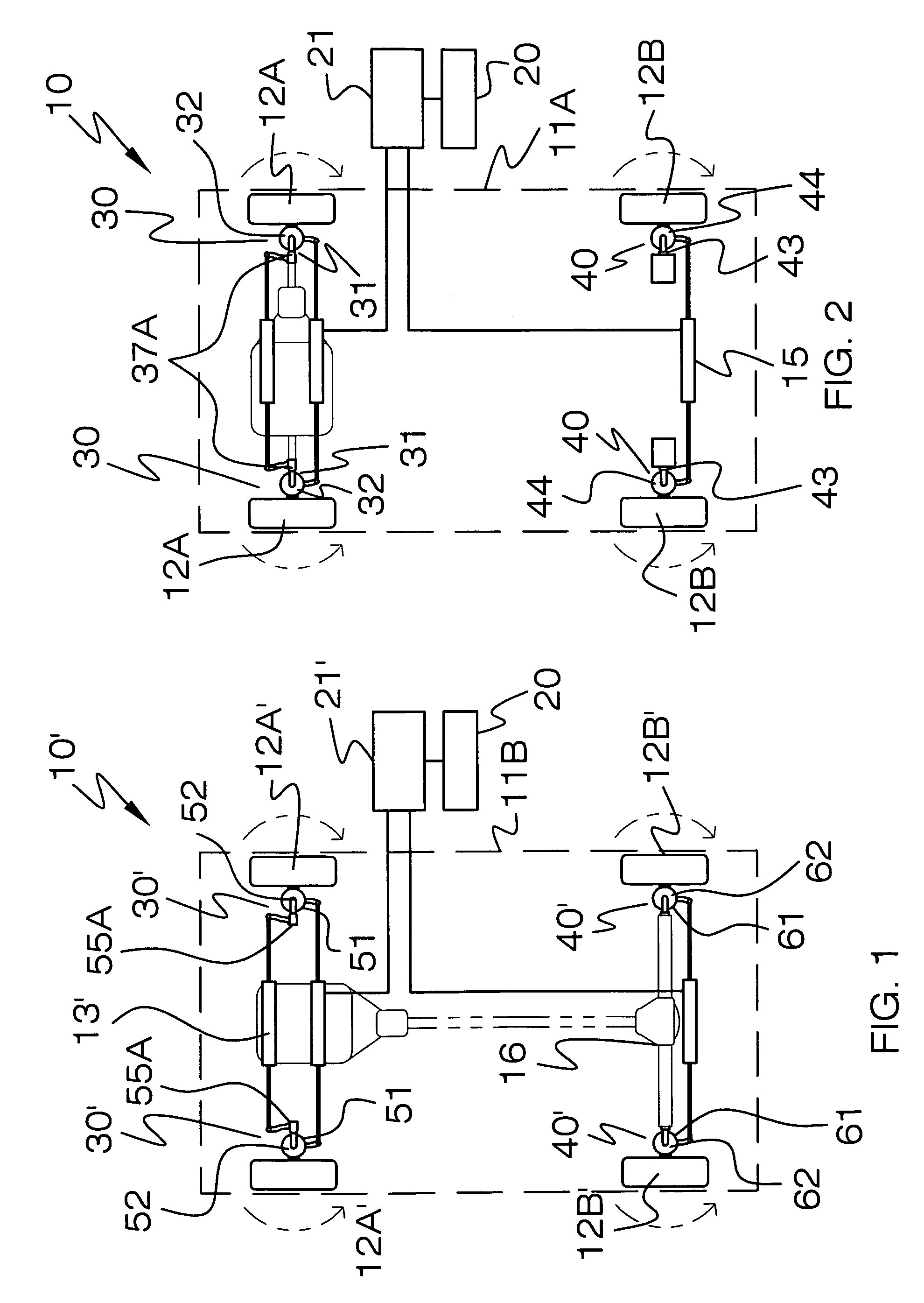
[0014]A controller is electrically coupled to the user interface. Such a controller receives the control output signal and automatically instructs the front wheel rotating mechanism and the rear wheel rotating mechanism to contemporaneously register the front and rear wheels orthogonal to a longitudinal length of the vehicle so that the vehicle can advantageously and effectively be laterally displaced without moving along a longitudinal path.
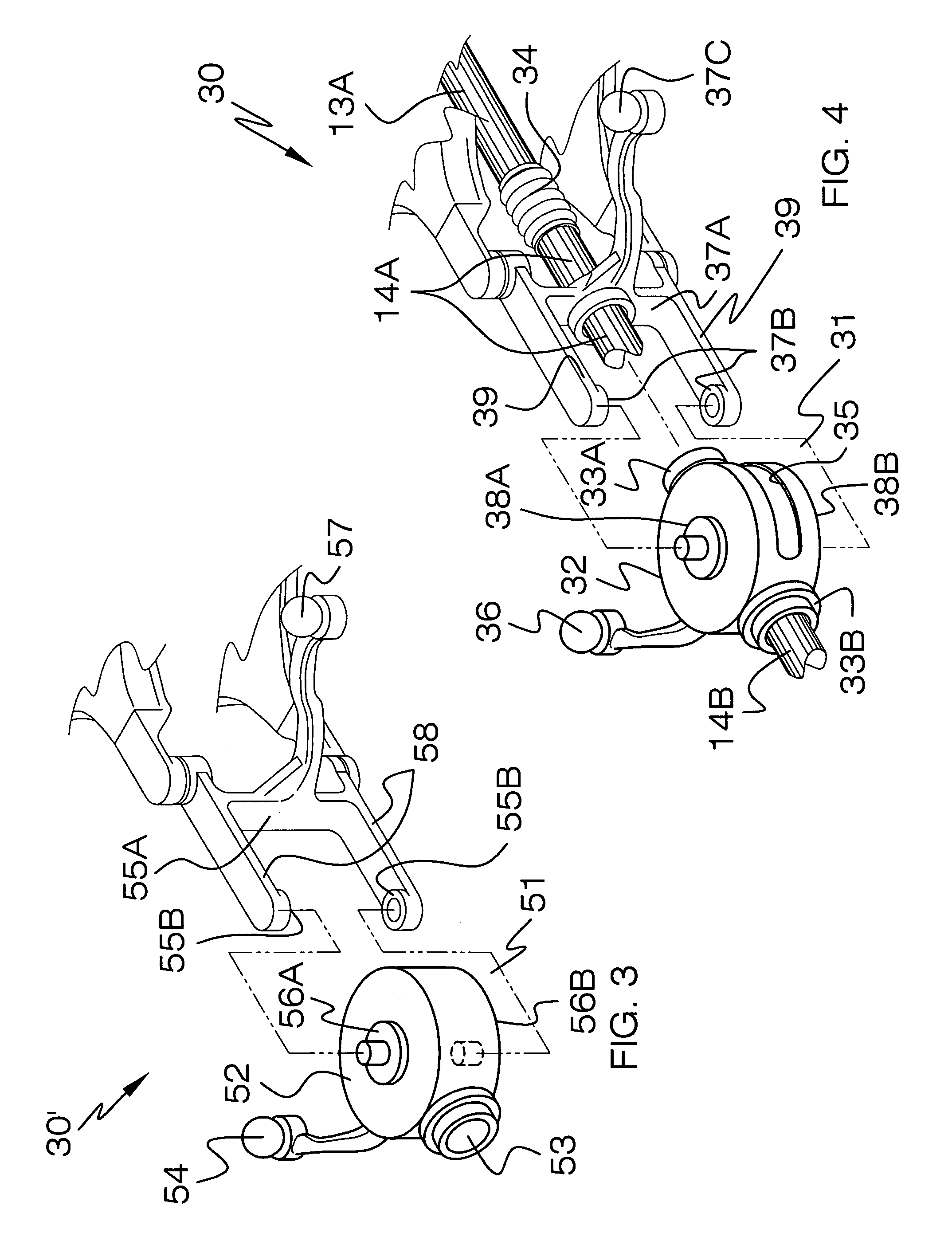
[0019]A pair of arms are directly conjoined to the flange portions. Such arms are operably coupled to the controller in such a manner that the arms effectively cause the spindles to articulate the housings based upon the user input signal. The laterally disposed driven axles and the housings rotate in sync along the arcuate paths and thereby effectively displace associated ones of the vehicles wheels parallel to the longitudinal length of the front wheel drive axle.
[0022]A pair of arms are directly conjoined to the flange portions. Such arms are operably coupled to the controller in such a manner that the arms effectively cause the spindles to articulate the housings based upon the user input signal. Such housings rotate in sync along the arcuate paths and thereby effectively displace associated ones of the vehicle's wheels parallel to the longitudinal length of the rear driven axle of the front wheel drive vehicle.
[0025]A pair of arms are directly conjoined to the flange portions. Such arms are operably coupled to the controller in such a manner that the arms effectively cause the spindles to articulate the housings based upon the user input signal. The housings rotate in sync along the arcuate paths and thereby effectively displace associated ones of the vehicles wheels parallel to the longitudinal length of the front driven axle of the rear wheel drive vehicle.
[0031]A pair of arms are directly conjoined to the flange portions. Such arms are operably coupled to the controller in such a manner that the arms cause the spindles to articulate the housings based upon the user input signal. The laterally disposed driven axles and the housings rotate in sync along the arcuate paths and thereby effectively displace associated ones of the vehicle's wheels parallel to the longitudinal length of the rear wheel drive axle.

Problems solved by technology

The conventional automobile type vehicle has a larger turning radius, which leads to the difficulty one encounters when trying to maneuver and position such a vehicle into a limited area of space.
During this time consuming procedure, one must often maneuver the vehicle backwards and forwards a number of times, while running the risk of striking the cars parked fore and aft of the limited space.
The conventional omni-directional vehicle of this type has a steering motor for each wheel and is thus expensive.
Synchronizing control devices are complicated and expensive.

Method used


Image

  • Auxiliary steering system for vehicles
  • Auxiliary steering system for vehicles
  • Auxiliary steering system for vehicles

Examples


Embodiment Construction

[0044]The present invention will now be described more fully hereinafter with reference to the accompanying drawings, in which preferred embodiments of the invention are shown. This invention may, however, be embodied in many different forms and should not be construed as limited to the embodiments set forth herein. Rather, these embodiments are provided so that this application will be thorough and complete, and will fully convey the true scope of the invention to those skilled in the art. Like numbers refer to like elements throughout the figures and prime numbers refer to alternate embodiments of such elements.

[0045]The system of this invention is referred to generally in FIGS. 1-9 by the reference numeral 10 and is intended to provide an auxiliary steering system for vehicles. It should be understood that the system 10 may be used to provide lateral movement of a vehicle in many different types of situations and should not be limited in use to only parallel parking situations.

[0...


PUM


Abstract

An auxiliary vehicle steering system includes a user interface for receiving a user input and transmitting a control output signal associated with the input signal. The interface is located within the vehicle. A mechanism is included for rotating a vehicle's front wheels along an arcuate path offset 90 degrees from equilibrium. The front wheel rotating mechanism includes grooved plates that have tapered outer edge portions extending along an outer perimeter thereof. A mechanism is included for rotating a vehicle's rear wheels along an arcuate path offset 90 degrees from equilibrium. The rear wheel rotating mechanism includes grooved plates that have tapered outer edge portions extending along an outer perimeter thereof. A controller is coupled to the interface that receives the control output signal and instructs the front wheel and the rear wheel rotating mechanisms to contemporaneously register the wheels orthogonal to the vehicle so that same can be laterally displaced.

Description

CROSS REFERENCE TO RELATED APPLICATIONS[0001]Not Applicable.STATEMENT REGARDING FEDERALLY SPONSORED RESEARCH OR DEVELOPMENT[0002]Not Applicable.REFERENCE TO A MICROFICHE APPENDIX[0003]Not Applicable.BACKGROUND OF THE INVENTION[0004]1. Technical Field[0005]This invention relates to steering systems and, more particularly, to an auxiliary steering system for vehicles for assisting a driver to laterally park a vehicle into space-limited areas.[0006]2. Prior Art[0007]Conventional vehicles with wheels are classified into two categories: automobile type vehicles, whose front or rear wheels are steered to change the direction in which vehicles travel, and omni-directional vehicles, whose wheels are all steered in a certain direction so that the vehicle can travel forward, backward, right, left, or diagonally without changing the vehicle position. The conventional automobile type vehicle has a larger turning radius, which leads to the difficulty one encounters when trying to maneuver and po...

Claims


Application Information

Patent Timeline
Patent Type & Authority Patents(United States)
IPC IPC(8): G06F17/00G06F19/00
CPCB60K17/30B62D7/1509B62D7/18
Inventor EPHRAIM, UBON B.
Owner EPHRAIM UBON B
Learn More