Electric switch

a technology of electric switch and switch body, which is applied in the direction of electric switch, contact mechanism, electrical apparatus, etc., can solve the problems of not being able to reduce the actuating displacement of the switch, and achieve the effect of reducing the installation space required for the switch and contributing to the compactness of the switch

Inactive Publication Date: 2005-11-15
MARQUARDT GMBH SCHLOSSTRASSE 16 7201 RIETHEIM-WEILHEIM 1 WEST GERMANY
View PDF16 Cites 3 Cited by
  • Summary
  • Abstract
  • Description
  • Claims
  • Application Information

AI Technical Summary

Benefits of technology

[0011]The lever may be pivotably mounted on a bearing in the housing of the switch. In a further configuration, the lever is formed as a one-armed lever. The bearing is then located at one end of the lever. Such a configuration also contributes to reducing the installation space required for the switch.
[0012]In one type of design of the switch, the switching contact is configured in the form of a rocker. One end of the lever, this being the end opposite from the bearing of the lever in the case of a one-armed lever, bears with an elastic force against the switching contact. When there is movement of the lever, the switching contact in the form of a rocker is then switched. This configuration ensures that the actuating force for moving the actuation member only has at most a slight influence on the contact force exerted by the switching contact. Furthermore, the lever may have a sleeve, in which a compression spring is arranged for exerting the elastic force. This compression spring acts on a control cam, which in turn acts on the switching contact, which likewise contributes to the compactness of the switch.
[0014]The electric switch is preferably configured as a short-stroke pushbutton switch. For this purpose, the actuation member is formed as a substantially linearly movable pushbutton. The pushbutton can be moved against the force of a spring and part of it protrudes out of the housing for manual access by the user. For particularly efficient and space-saving articulation of the lever on the pushbutton, the lever passes through a receptacle on the actuation member, which is arranged on the part of the actuation member located inside the housing of the switch, approximately transversely with respect to the direction of movement of the actuation member. Consequently, when there is movement of the actuation member, the lever pivots in a simple way.
[0015]In another type of design of the switch, the contact system is formed as a snap-action contact system. For this purpose, the switching contact is configured as a snap-action switching contact, so that, when there is movement of the lever, the switching contact switches between its two end positions with snapping action. The switching contact is pivotably mounted in a knife-edge bearing, which may be arranged for example at an electrical terminal. A tension spring is fastened by one end to the switching contact and by the other end to the lever. The fastening to the lever may be located on the side opposite from the bearing of the lever. Such a snap-action contact system advantageously offers lower actuating forces and lower noise development than some other contact system.
[0019]The advantages achieved by the invention are, in particular, that the switch can be operated with a short actuating displacement. The short-stroke switch according to the invention allows a uniform operator control philosophy, for example in domestic appliances, where a short-stroke circuit breaker can be used in the control panel for disconnecting the power in addition to the already customary short-stroke buttons for the logic control.

Problems solved by technology

On the other hand, a reduction in the actuating displacement of the switch does not appear to be possible on account of the technical specifications to be considered, such as for example the various tolerance positions of the individual parts of the switch, the contact erosion in the contact system occurring over the lifetime of the switch, the contact opening clearance required for the switching of high power of at least 3 mm, the application of the necessary contact force, the reliable function of the switch, or the like.

Method used


Image

  • Electric switch
  • Electric switch
  • Electric switch

Examples


Embodiment Construction

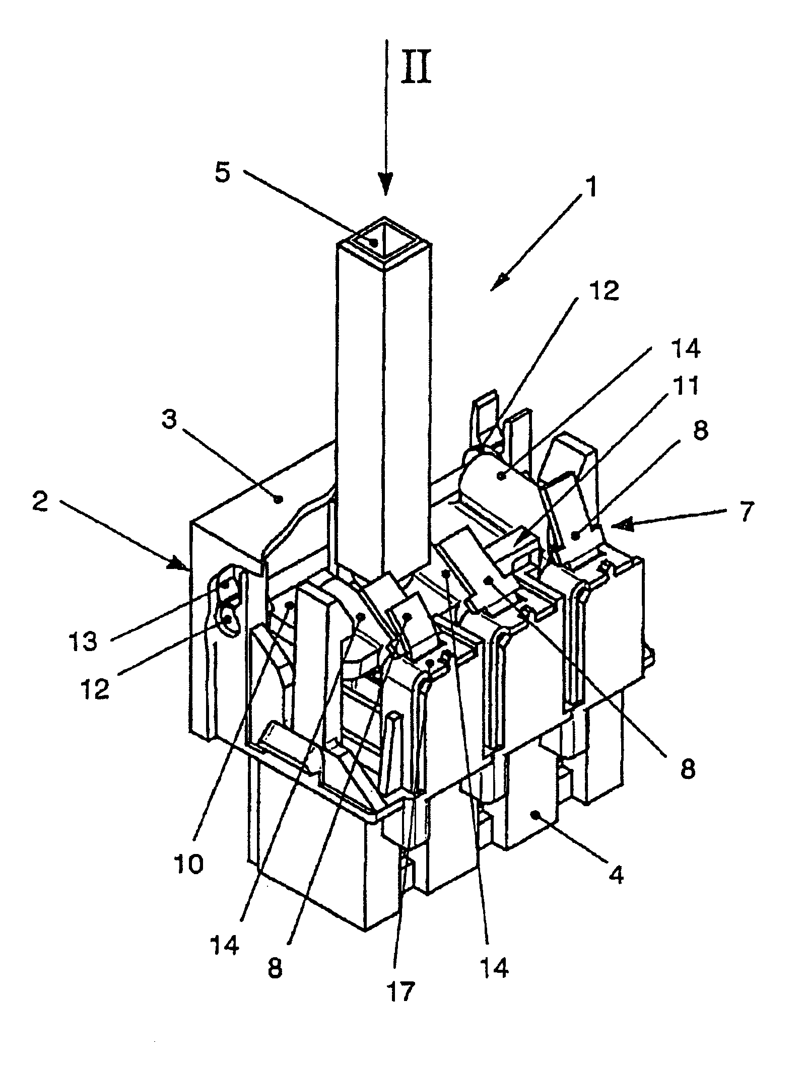
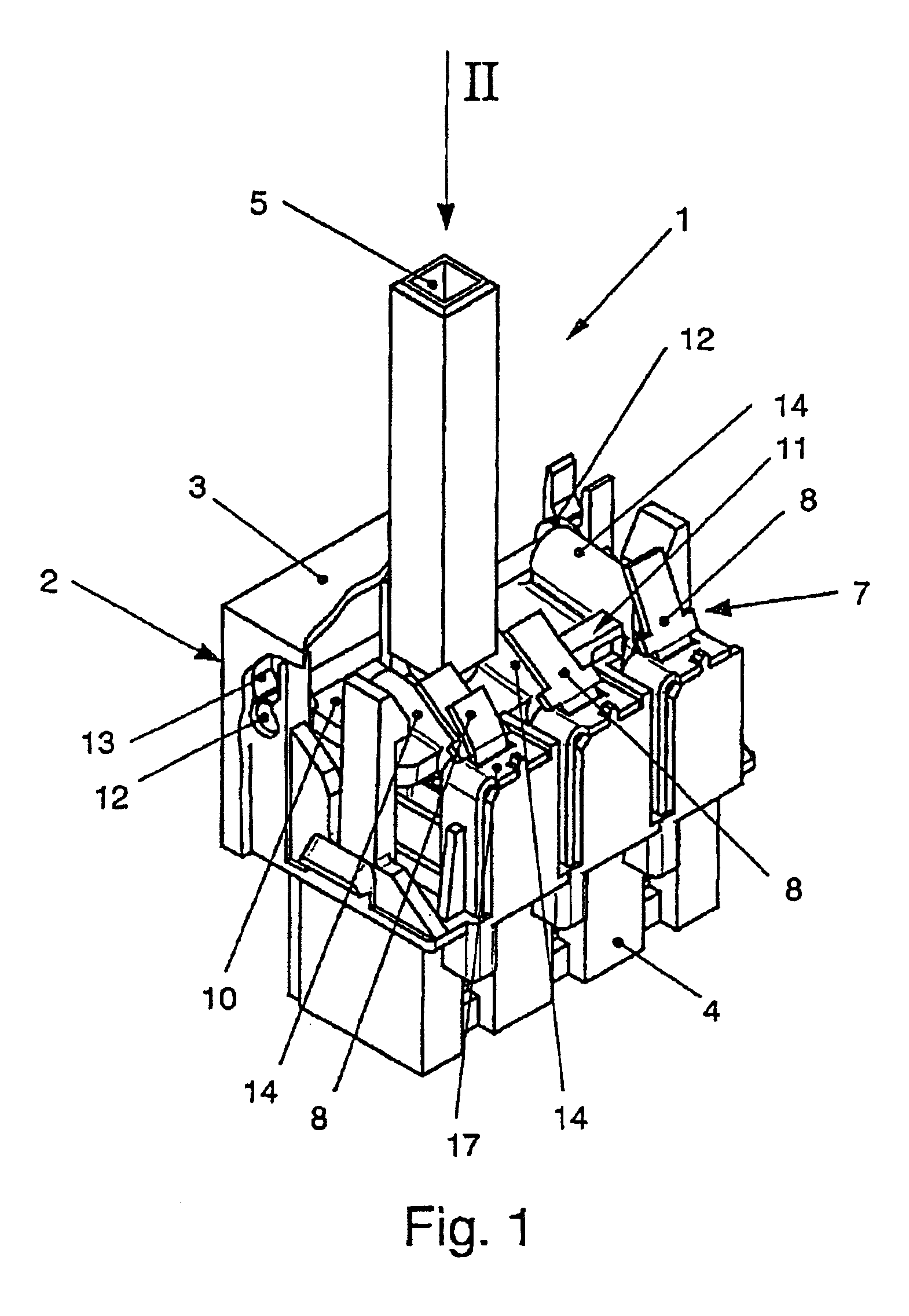
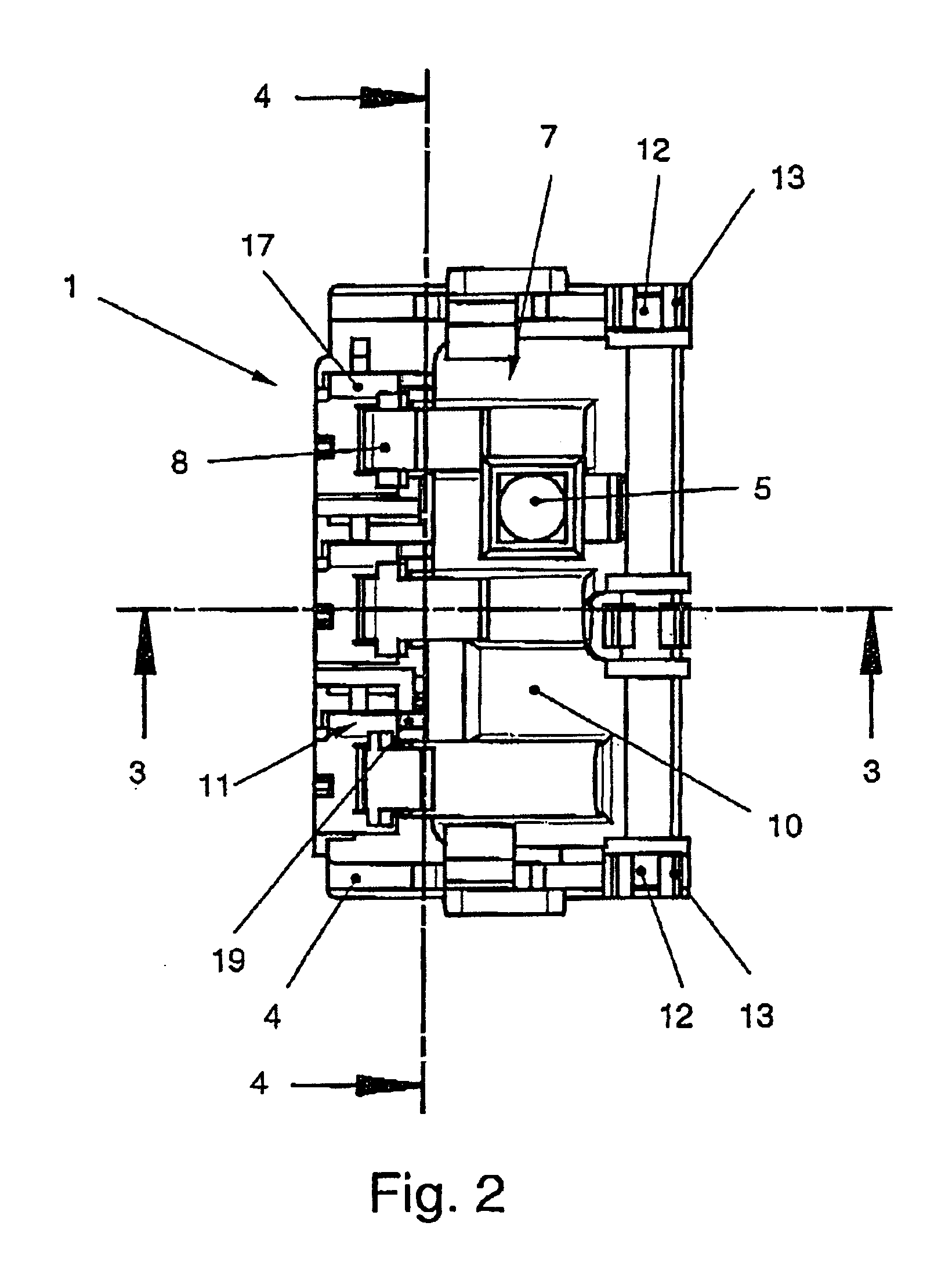
[0032]Shown in FIG. 1 is an electric switch 1 according to a first exemplary embodiment, which is suitable for switching a high load. The switch 1 may be used for example as a power switch for an electrical appliance. The switch 1 has a housing 2, which in FIG. 1 is merely represented in a schematic and broken-open form and comprises a cover 3 and a base 4. Protruding out of the housing 2 on the upper side of the cover 3 is an actuation-member 5. The part of the actuation member 5 protruding from housing 2 is accessible to the user for manual operation of the switch 1. The actuation member 5 is formed in the present case as a pushbutton which can be moved substantially linearly against the force of a spring 20, as can be seen in FIG. 4. On the underside, the electrical terminals 6 of the switch 1 that can be seen in FIG. 3 are located in the base 4.

[0033]The switch 1 has a three-pole contact system 7, as can be seen from FIG. 1. As FIG. 3 also reveals, the contact system 7 comprises...


PUM


Abstract

An electric switch, in particular for a high load, such as a power switch. The switch has a contact system comprising a movable switching contact and at least one stationary contact. A movable actuation member, when moved, interacts with the switching contact for the purpose of switching the contact system. If appropriate, the switch may also have a movable locking means, which interacts with the actuation member in an interlocking manner. The actuation member is in operative connection with a lever in such a way that, when there is movement of the actuation member, the lever carries out a pivoting movement. The pivoting movement of the lever moves the switching contact for the purpose of switching and / or the locking means for the purpose of interlocking, in particular with increasing transformation of the displacement covered by the actuation member.

Description

CROSS REFERENCE TO RELATED APPLICATIONS[0001]This application is a continuation of International Application No. PCT / DE02 / 04039 having an international filing date of Oct. 30, 2002, which designated the United States, the entirety of which is incorporated herein by reference.[0002]This application also claims the benefit of German Application No. 101 53 871.5, filed Nov. 2, 2001, and German Application No. 102 22 498.6, filed May 22, 2002, the entireties of which are incorporated herein by reference.FIELD OF THE INVENTION[0003]The invention relates to an electric switch according to the precharacterizing clause of patent claim[0004]In electrical and domestic appliances, for example washing machines, dishwashers or the like, electric switches serve as power switches. For this purpose, the switch must be suitable for switching a high load.BACKGROUND OF THE INVENTION[0005]Such an electric switch is known for example from DE 42 02 214 A1. This switch has a contact system comprising a mo...

Claims


Application Information

Patent Timeline
Patent Type & Authority Patents(United States)
IPC IPC(8): H01H13/50H01H13/12H01H13/56H01H13/60H01H13/20H01H9/00
CPCH01H13/20H01H13/562H01H13/60H01H9/0072
Inventor WOLBER, RALPHKIZELE, RAINERMULLER, HEINRICHMEJERL, THOMAS
Owner MARQUARDT GMBH SCHLOSSTRASSE 16 7201 RIETHEIM-WEILHEIM 1 WEST GERMANY
Why Eureka
Try Eureka