Deflector for spiral separator, and method of spiral separation

a technology of spiral separator and separator, which is applied in the direction of solid separation, sieving, screening, etc., can solve the problem that the deflector device is somewhat limited

Inactive Publication Date: 2010-03-30
MINERAL TECH
View PDF6 Cites 4 Cited by
  • Summary
  • Abstract
  • Description
  • Claims
  • Application Information

AI Technical Summary

Benefits of technology

[0010]The present invention seeks to provide a deflector device which has a more refined action and has much greater scope for influencing the stream in a spiral separation, to enhance separation.
[0024]Also preferably, said device is weighted or tensioned for heavier action (heavier fan) or unweighted for lighter action by adjusting the flexibility, weight, tension and / or tightness of the arm member or the like.

Problems solved by technology

In particular, that device interrupts a portion of low density, high water content, stream from the ‘tailing zone’ and sprays or redeposits it into the high density, low water content, ‘middling zone’.
Whilst the deflector of Australian Patent Serial No. 575046 improved the recovery of minerals, due to the inability for the device to be readily adjusted, and due to its somewhat inflexible design, the deflector device has been found to be somewhat limited, identifying a need for an improved product thereto.

Method used


Image

  • Deflector for spiral separator, and method of spiral separation
  • Deflector for spiral separator, and method of spiral separation
  • Deflector for spiral separator, and method of spiral separation

Examples


Embodiment Construction

[0035]Throughout the drawings, like numerals will be used to identify similar features, except where expressly otherwise indicated.

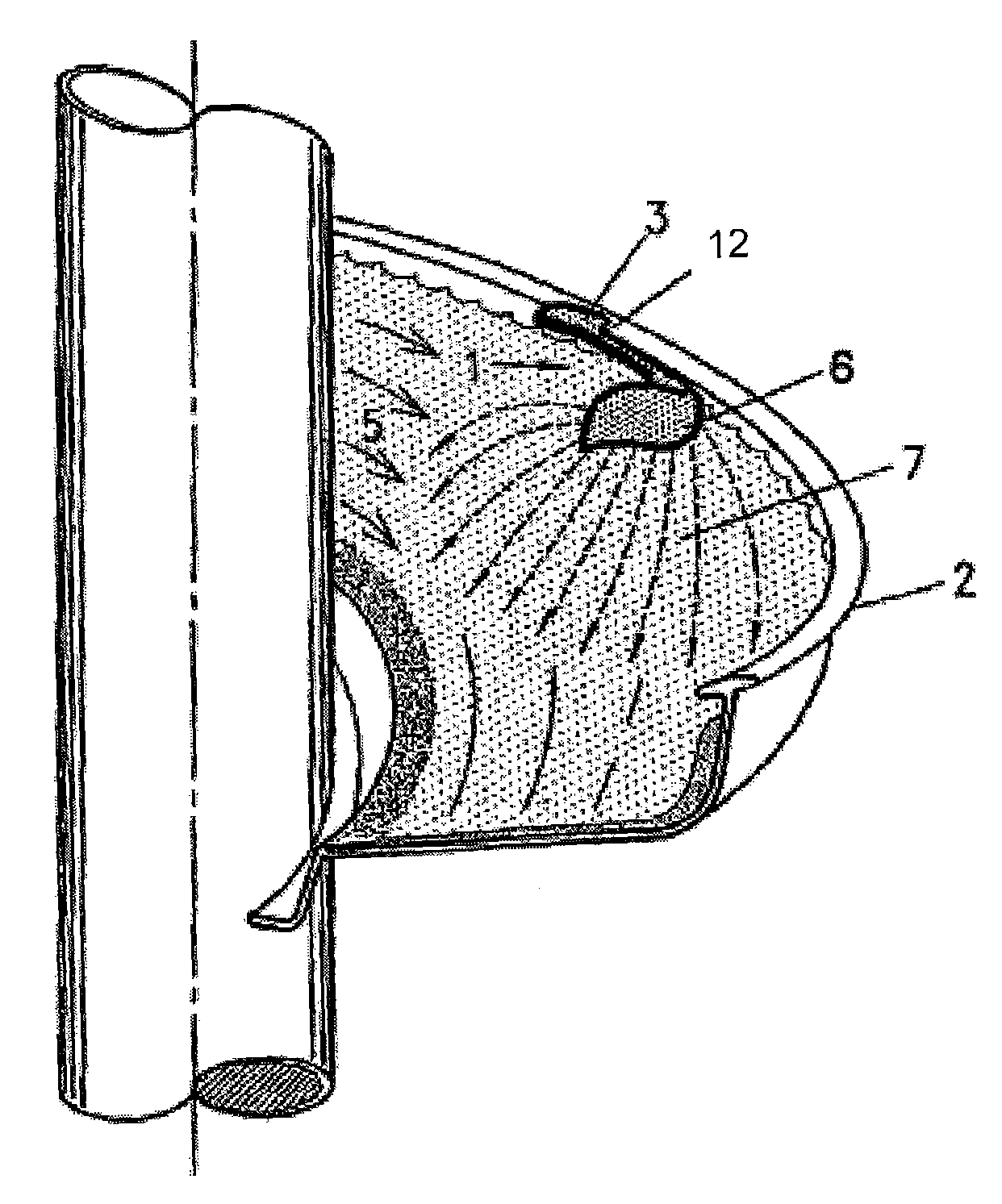
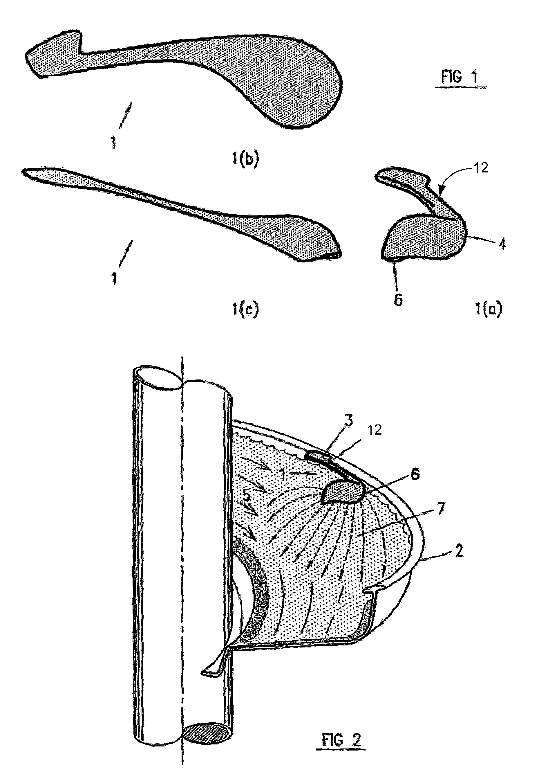
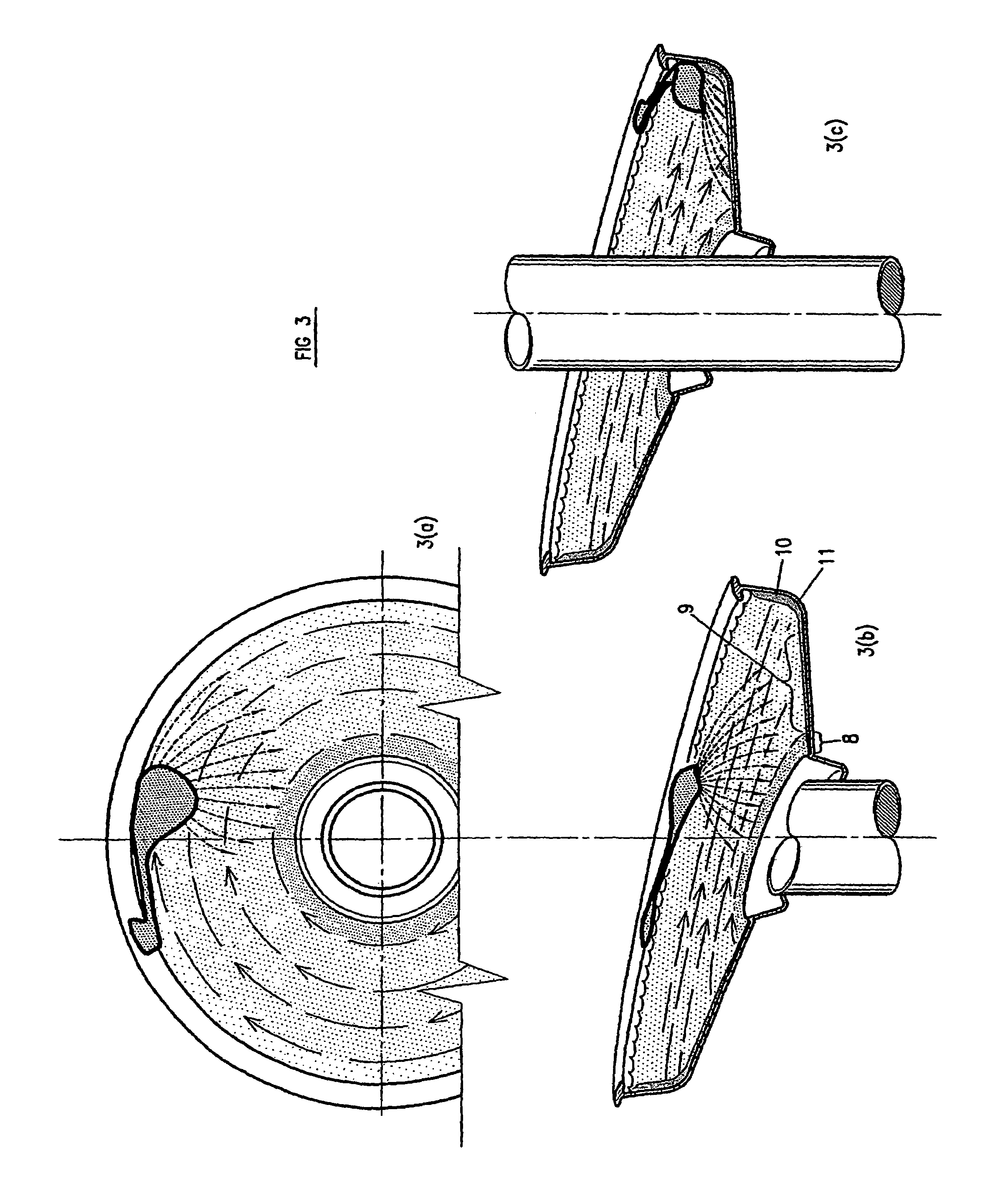
[0036]As shown in the drawings, the deflector, generally designated by the numeral I, is adapted to be attached to a spiral separator, generally designated by the numeral 2. The deflector 1 is designed to capture and redirect a controlled portion of the flowing stream of material flowing through the spiral separator. The deflector 1, generally includes an attachment means 3, for attachment of the deflector 1 to the spiral separator 2, a capturing portion 4 shaped to substantially ride atop and capture a portion of the flowing stream of material 5, and a redirecting portion 6, which is integrally formed with the capturing portion 4, and which is shaped to spray or otherwise emit the captured material, as illustrated by reference numeral 7. The spray 7 may be patterned to be of any desired shape, depending upon the desired pattern of the spray as it re-ent...


PUM


Abstract

A deflector (1) for attachment to a spiral separator (2), for capturing and redirecting a portion of a flowing stream of material (5). The deflector (1) includes an attachment means (3), to attach the deflector (1) to the spiral separator (2), a capturing portion (4) to capture a portion of the flowing stream (5), and, a redirecting portion (6) to emit a portion (7) of the stream. A method of separating particles of different densities using the deflector device (1) in conjunction with a spiral separator (2) is also disclosed.

Description

[0001]This application is a continuation of U.S. patent application Ser. No. 10 / 478,043, filed Jun. 7, 2004 now abandoned, which claims priority of PCT Patent Application No. PCT / AU02 / 00602, filed May 17, 2002.BACKGROUND OF THE INVENTION[0002]The present invention relates to a spiral separator and to a method of spiral separation, and in particular, to a deflector to use in a spiral separator and method of spiral separation. In particular, the present invention relates to the use of such a deflector for the improved separation of particles of different densities.DESCRIPTION OF THE PRIOR ART[0003]The reference to any prior art in this specification is not, and should not be taken as, an acknowledgement or any form of suggestion that that prior art forms part of the common general knowledge in Australia.[0004]Spiral separators are extensively used for the wet gravity separation of solids 15 according to their specific gravity, for example, for separating various kinds of mineral sands...

Claims


Application Information

Patent Timeline
Patent Type & Authority Patents(United States)
IPC IPC(8): B07B1/08B03B5/00B07B11/00
CPCB03B5/626
Inventor PALMER, MARK KENNETH
Owner MINERAL TECH
Why Eureka
Try Eureka