Recording apparatus

a recording apparatus and nozzle technology, applied in the direction of printing, other printing apparatus, etc., can solve the problems of increasing the number of nozzle columns, the difficulty of increasing the recording speed, and the number of circuits

Inactive Publication Date: 2010-03-30
CANON KK
View PDF3 Cites 2 Cited by
  • Summary
  • Abstract
  • Description
  • Claims
  • Application Information

AI Technical Summary

Benefits of technology

[0019]The primary object of the present invention is to realize an innovative controlling method for driving a recording head, and a control circuit for driving a recording head, in order to solve the above described problems.

Problems solved by technology

To begin with, an increase in the number of nozzles in a nozzle column increases the length of time necessary to drive all the blocks in each nozzle column per scan, making it difficult to increase recording speed.
However, this arrangement is also problematic in that it requires an increase in the number of nozzle columns, and also, the number of circuits for controlling the process of driving the nozzle blocks.
Further, it is limited in the number of the recording head driving methods, from which an optimal method can be selected, and also, in the number of the recording patterns, from which an optimal pattern can be selected.
Thus, the circuit designed for controlling the block-based driving method in accordance with the prior art becomes problematic in that it has to be made more complicated and increased in size to solve the above described problems.

Method used


Image

  • Recording apparatus
  • Recording apparatus
  • Recording apparatus

Examples


embodiment 1

[0062]FIG. 4(A) shows the nozzle column arrangement of the recording head 1. Two odd number nozzle columns (odd1 and odd2) and two even number nozzle columns (even1 and even2) are provided per color. The four nozzle columns are selectively driven to form a single line of dots on the recording medium.

[0063]As shown in FIG. 4(A), the nozzles (indicated by circles in drawing) in each nozzle column are aligned in the direction (vertical direction in drawing: secondary scan direction) perpendicular to the direction in which the recording head 1 scans recording medium (leftward and rightward directions in drawing). The recording head 1 is set up so that a given odd number nozzle column and the even number nozzle column paired with this odd number nozzle column record the picture elements having odd ordinal numbers (counting from top side of head) and the picture elements having even ordinal numbers. In the case of the recording head 1 in the drawing, the recording head 1 is structured so ...

embodiment 2

[0096]FIG. 4(B) shows the nozzle arrangement of the recording head 1, which is different from the one shown in FIG. 4(A). In this case, four nozzle columns (odd1, odd2, odd3, and odd4) of nozzles having an odd number are provided per color, and also, four nozzle columns (even1, even2, even3, and even4) of nozzles having an even number are provided per color.

[0097]A single line of dots can be formed on recording medium by selectively driving these eight nozzle columns.

[0098]This embodiment is different from the first one in the number of the nozzles columns of the recording head. Otherwise, this embodiment is the same as the first one in terms of recording head structure. Thus, the structure of the recording head in this embodiment will not be described.

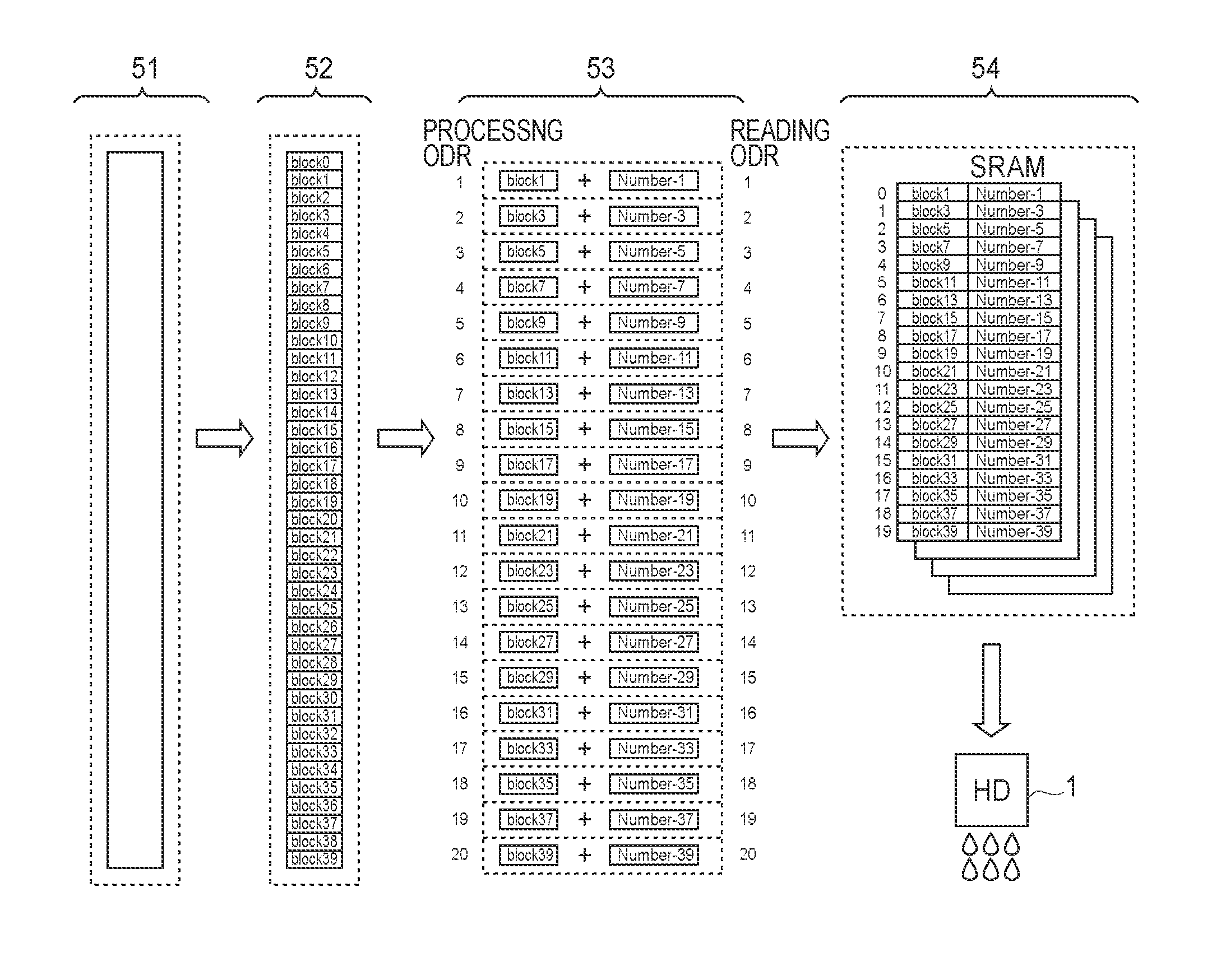
[0099]FIG. 9 is a schematic drawing, which is similar to FIG. 5 which was used to describe the first embodiment.

[0100]A nozzle data 91 is the same as the nozzle data 51. A block data 92 is the same as the block data 52. The driving da...

embodiments 1 and 2

Control Sequences in Embodiments 1 and 2

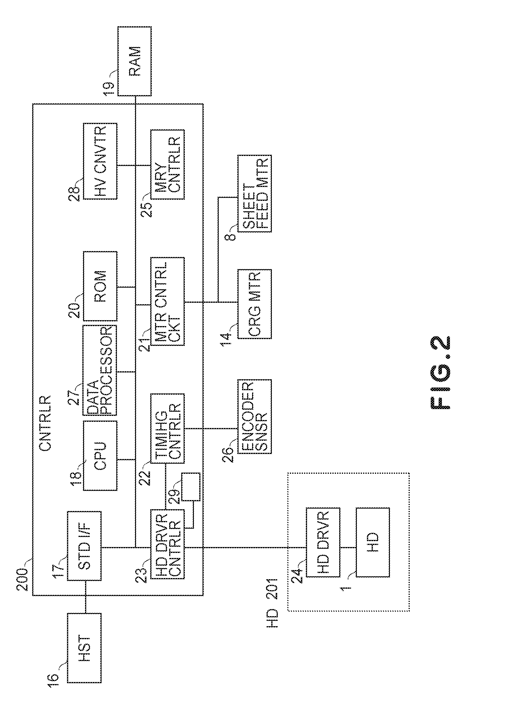
[0124]Next, referring to FIG. 12, the control sequences carried out by the recording process controlling portion 200 will be described. This control sequence is carried out primarily by the CPU 18. The control sequence shown in FIG. 12 is stored the ROM 12 or the like.

[0125]In Step S121, the nozzle data are read out from the print buffer. In Step S122, the nozzle data are converted into block data. In Step S123, the driving data having both the block number and block data are stored in the transfer buffer.

[0126]In Step S124, it is checked whether or not the driving data for the number of the nozzle blocks in each of the nozzle columns to be used for recording have been stored. For example, in the case of the first embodiment, it is checked whether or not the driving data for 20 nozzle blocks have been processed and stored.

[0127]In Step S125, if the answer is No, the control portion 200 returns to Step S123 and continues the sequence. If the an...


PUM


Abstract

A recording apparatus for effecting recording by scanningly moving a recording head, wherein the apparatus is provided with a group of a plurality of arrays each including a plurality of nozzles, wherein the group is responsive to one-color recording data, includes selecting means for selecting a block of a predetermined number of the nozzles in the nozzle array in synchronism with cyclic signals; driving means for driving the nozzles in the block selected by the selecting means; managing means for managing information of the block selected by the selecting means, for each group of the nozzle arrays; generating means for generating, for each nozzle array, driving data including information indicative of a block to be selected by the selecting means and block data corresponding to the block, on the basis of the information of the block managed by the managing means; and transfer means for transferring the driving data generated by the generating means to the recording head.

Description

FIELD OF THE INVENTION AND RELATED ART[0001]The present invention relates to a recording apparatus which records with the use of a recording head characterized in that it is provided with multiple columns of nozzles controllable according to the recording data for each of the colors in which it is capable of recording. The present invention also relates to a method for controlling such a recording apparatus.[0002]A printer has been widely used as an information outputting apparatus for a personal computer, facsimile machine, etc.[0003]There have been known various recording methods for a printer. In recent years, however, an ink jet recording method has been attracting a large amount of attention, for various reasons such as it can record with no contact between a recording head and recording medium such as sheet of paper, can be easily devised to record in color, is quiet, etc.[0004]Among various ink jet printers, an ink jet printer of the serial type, which records by moving its r...

Claims


Application Information

Patent Timeline
Patent Type & Authority Patents(United States)
IPC IPC(8): B41J29/38
CPCB41J2/04543B41J2/04586
Inventor FUJIMOTO, KAZUSHI
Owner CANON KK
Why Eureka
Try Eureka