Cyclone dust collection apparatus

a dust collection and cyclone technology, applied in the field of vacuum cleaners, can solve the problems of increasing the height of the dust collection apparatus, applied to the canister-type cleaner, etc., and achieve the effect of reducing the loss of suction for

Inactive Publication Date: 2010-03-30
SAMSUNG GWANGJU ELECTRONICS CO LTD
View PDF17 Cites 83 Cited by
  • Summary
  • Abstract
  • Description
  • Claims
  • Application Information

AI Technical Summary

Benefits of technology

[0010]Accordingly, the present invention has been made to solve the above-mentioned problems occurring in the prior art, and an object of the present invention is to provide a cyclone dust collection apparatus, wherein an air flow path for air discharged from the cyclone dust collection apparatus to a motor driving chamber is reduced so as to decrease a loss in suction force.
[0011]Another object of the invention is to provide a cyclone dust collection apparatus having a first cyclone which is improved in fine dust collection efficiency so as to enhance a convenience in using the cyclone dust collection apparatus.

Problems solved by technology

However, such conventional multi-clone dust collection apparatus has a disadvantage in that that because an upstream cyclone (a first cyclone), and a downstream cleaner (a second cyclone) are vertically arranged, thereby increasing the entire height of the dust-collection apparatus, they are mainly applied to an upright type cleaner but hard to be applied to a canister-type cleaner.

Method used


Image

  • Cyclone dust collection apparatus
  • Cyclone dust collection apparatus
  • Cyclone dust collection apparatus

Examples


Embodiment Construction

[0027]Hereinbelow, the preferred embodiments of the present invention are described in detail with reference to accompanying drawings.

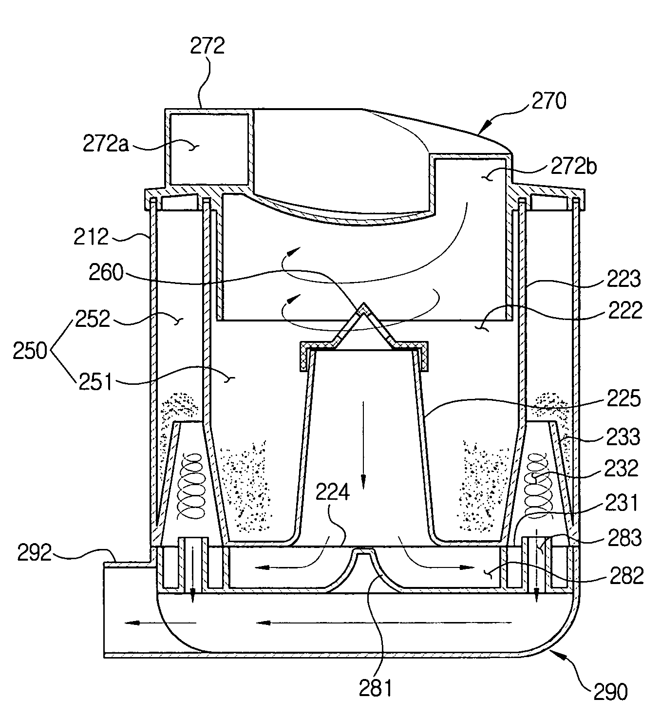
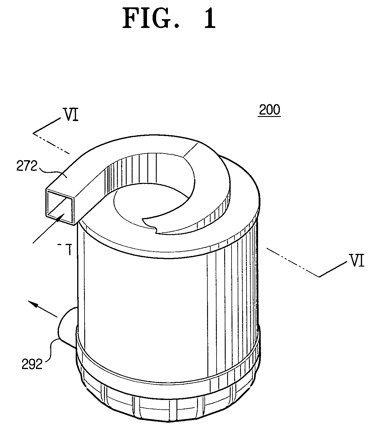
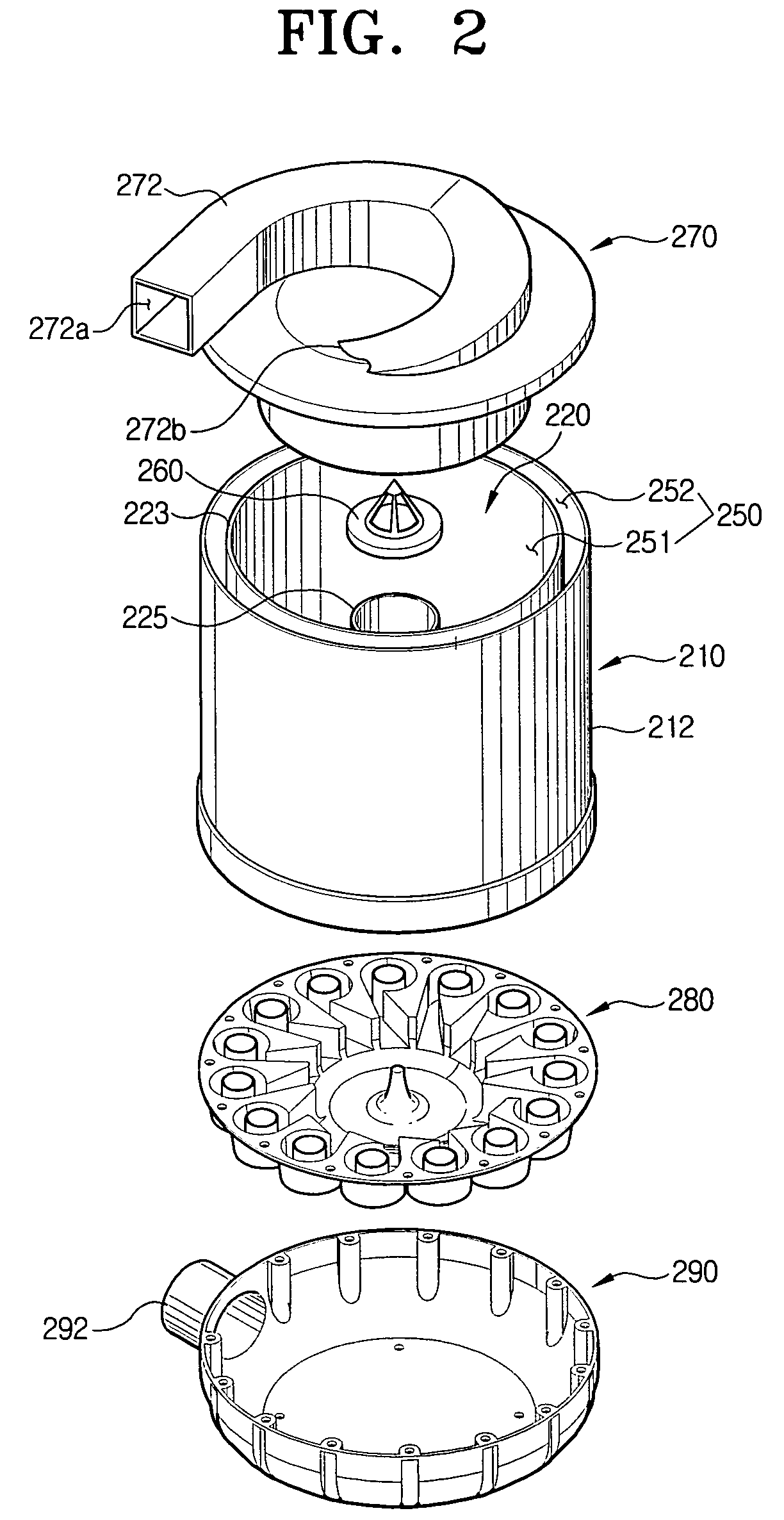
[0028]Referring to FIGS. 1 to 3, a cyclone dust collection apparatus 200 comprises a cyclone body 210, a top cover 270, an inflow / outflow guide cover 280, and a discharge cover 290.

[0029]The cyclone body 210 causes dust containing air introduced from the outside to form a swirling stream and filters the dust from the air over two steps. Referring to FIGS. 2 and 6, a first cyclone section 220 comprises a first chamber outer wall 223 defining a first cyclone chamber 222, an air outlet 224, and an air discharging pipe 225. The first cyclone chamber 222 causes the dust containing air introduced from an air inflow duct 272 of the top cover 270 to form the swirling stream, thereby separating the air and the dust. The air outlet 224 is formed in lower end of the first cyclone chamber 222, through which the air is discharged after the dust is removed from the...


PUM

PropertyMeasurementUnit
particle diameteraaaaaaaaaa

Abstract

Disclosed is a cyclone dust collection apparatus. The cyclone apparatus comprises a cyclone body having a first cyclone section and a plurality of cyclone cones arranged around a lower part of the first cyclone, each cyclone cone having a conical shape whose diameter is reduced as approaching the top end thereof; a top cover joined to the top end of the cyclone body and formed with a helical air inflow duct for introducing ambient air into the first cyclone section; an inflow / outflow guide cover joined to the lower end of the cyclone body so as to communicate the first cyclone section and the plurality of cyclone cones; and a discharge cover joined to the lower part of the inflow / outflow guide cover so as to collect the air discharged through the inflow / outflow guide cover and discharge the collected air to the outside of the cyclone dust collection apparatus.

Description

CROSS-REFERENCE TO RELATED APPLICATIONS[0001]This application claims the benefit of Korean Patent Application No. 2005-95101 filed on Oct. 10, 2005 with the Korean Intellectual Property Office, the disclosure of which is incorporated herein by reference.BACKGROUND OF THE INVENTION[0002]1. Field of the Invention[0003]The present invention relates to a vacuum cleaner. In particular, the present invention relates to a cyclone dust collection apparatus, which is employed in a vacuum cleaner so as to filter dust suctioned from a surface together with air, using centrifugal force.[0004]2. Description of the Related Art[0005]In general, a vacuum cleaner comprises a bottom brush for suctioning dust from a surface together with air, a motor driving chamber provided with a driving source, and a vacuum cleaner body provided with a cyclone collection apparatus.[0006]The cyclone collection apparatus is constructed in such a way that dust-entrained air, which is introduced from the bottom brush, ...

Claims


Application Information

Patent Timeline
Patent Type & Authority Patents(United States)
IPC IPC(8): B01D45/12
CPCB04C5/04B04C5/26A47L9/1625A47L9/1641A47L9/165A47L9/1658A47L9/1666A47L9/1683Y10S55/03A47L9/10A47L9/16
Inventor OH, JANG-KEUN
Owner SAMSUNG GWANGJU ELECTRONICS CO LTD
Why Eureka
Try Eureka