Weather strip

a weather strip and strip technology, applied in the field of weather strips, can solve the problems of insufficient bonding force, inability to ensure desired strength (or shape holding performance), and weather strip cannot always be sufficiently lightened, so as to reduce the weight of the strip, the effect of suppressing the reduction of strength and bonding for

Active Publication Date: 2010-03-30
TOYODA GOSEI CO LTD
View PDF10 Cites 4 Cited by
  • Summary
  • Abstract
  • Description
  • Claims
  • Application Information

AI Technical Summary

Benefits of technology

[0009]The invention is accomplished to solve the aforementioned problems. An object of the invention is to provide a weather strip enabled to suppress reduction of the strength and the bonding force, while reducing the weight thereof.
[0012]According to (1), a predetermined bonding force is given by the metal insert embedded in the trim portion. Thus, the mounted state of the weather strip is maintained. Meanwhile, according to (1), each of the piece portions constituting the insert includes the vehicle interior side wall corresponding part, the vehicle exterior side wall corresponding part, and the connecting portion corresponding part and is substantially U-shaped in cross section. Both of the continuously connecting part between the vehicle interior side wall corresponding part and the connecting portion corresponding part and the continuously connecting part between the vehicle exterior side wall corresponding part and the connecting portion corresponding part are curved parts. Additionally, as compared with thicknesses of both the curved parts of the insert, thicknesses of the remaining parts of the insert other than both the curved parts are set to be small. Thus, the weather strip other than both the curved parts is formed to be thin. Accordingly, the entire insert, thus, the entire weather strip can be lightened. On the other hand, because the insert is not entirely thinned so that both of the curved parts are relatively thick, predetermined strength and stiffness can be ensured, so that the initial shape at the bending can easily be maintained. Consequently, a situation, in which the bonding force is insufficient, can be restrained from occurring. Thus, the mounted state can be stabilized. This enables the seal portion to exert sealing performance over a long period of time.
[0017]According to (3), an insert configured to change a thickness according to the position of a part thereof, at which the thickness is measured, can be relatively stably obtained. That is, generally, an insert is manufactured by extending a plate-like material by applying pressure thereto using rolling mill rollers. However, in this case, it is necessary to provide a difference in thickness between a part, which corresponds to each of both the curved parts, and each of the remaining parts other than both the curved parts. Regarding this respect, a predetermined step-like part is formed on the surface of the rolling mill roller. Then, a rolling process is performed on the plate-like material. Consequently, the above-described insert can accurately and stably be obtained with a relatively simple configuration.
[0019]According to (4), an end part of at least one of the vehicle interior side wall corresponding part and the vehicle exterior side wall corresponding part is cut off at predetermined intervals. Thus, the weather strip can be further lightened. On the other hand, objects to be cut are end parts of the vehicle interior side wall corresponding part and the vehicle exterior side wall corresponding part. Additionally, the end parts are cut at the predetermined intervals (e.g., every two end parts or every three end parts). This does not much affect the strength and the stiffness.

Problems solved by technology

Thus, the weather strip cannot always sufficiently be lightened.
On the other hand, when even the piece portions are formed to be thin to fit to the center bond portion, a desired strength (or shape holding performance) cannot be assured.
Consequently, the bonding force is insufficient.

Method used


Image

  • Weather strip
  • Weather strip
  • Weather strip

Examples


Embodiment Construction

[0028]Hereinafter, an embodiment of the invention is described in detail with reference to the accompanying drawings.

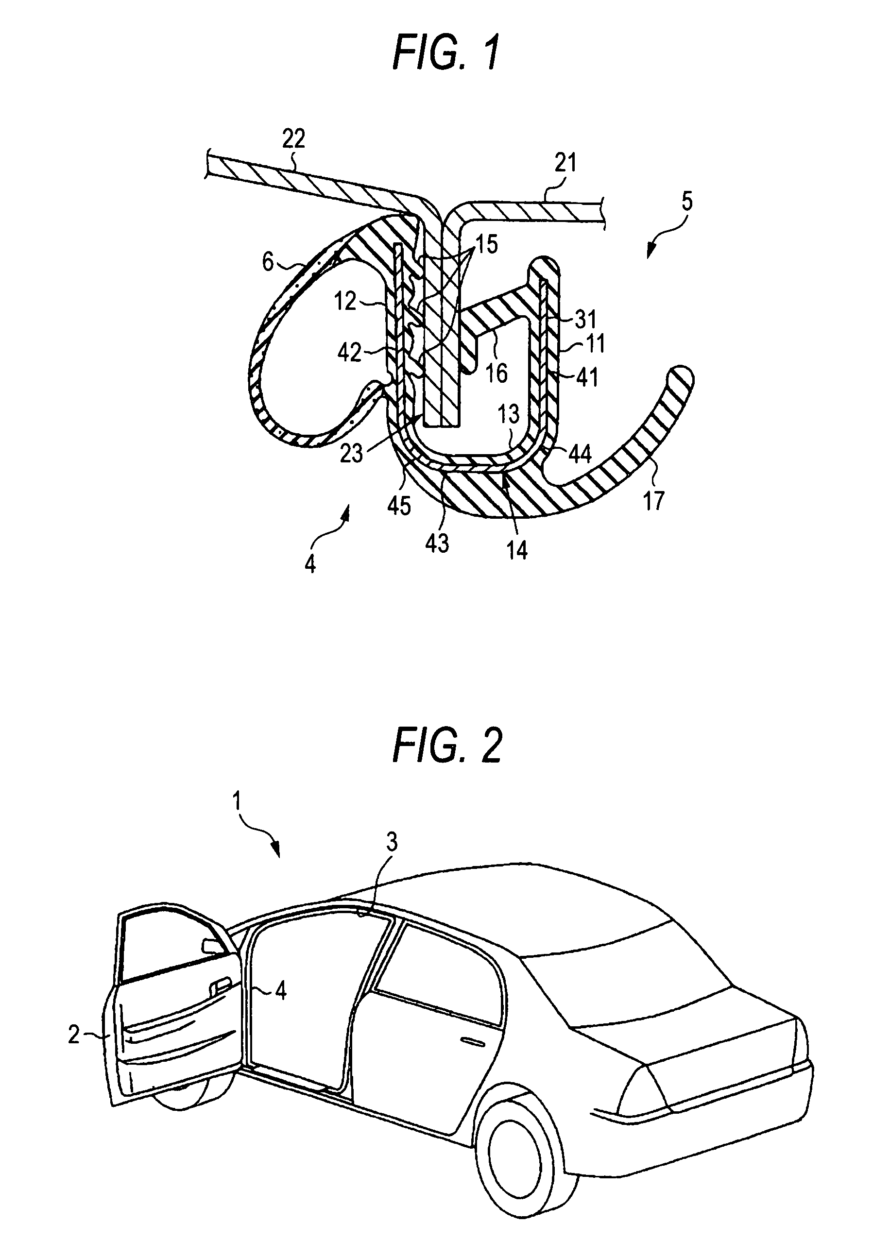
[0029]As illustrated in FIG. 2, a weather strip 4 is provided on a peripheral part of a body-side door opening 3 corresponding to a side door 2 of an automobile 1. The weather strip 4 according to the present embodiment is mounted on the peripheral part of the door opening 3 other than a lower part thereof. The entire weather strip 4 is formed by extrusion-molding.

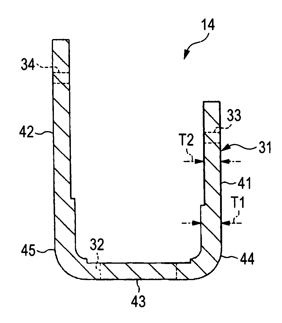
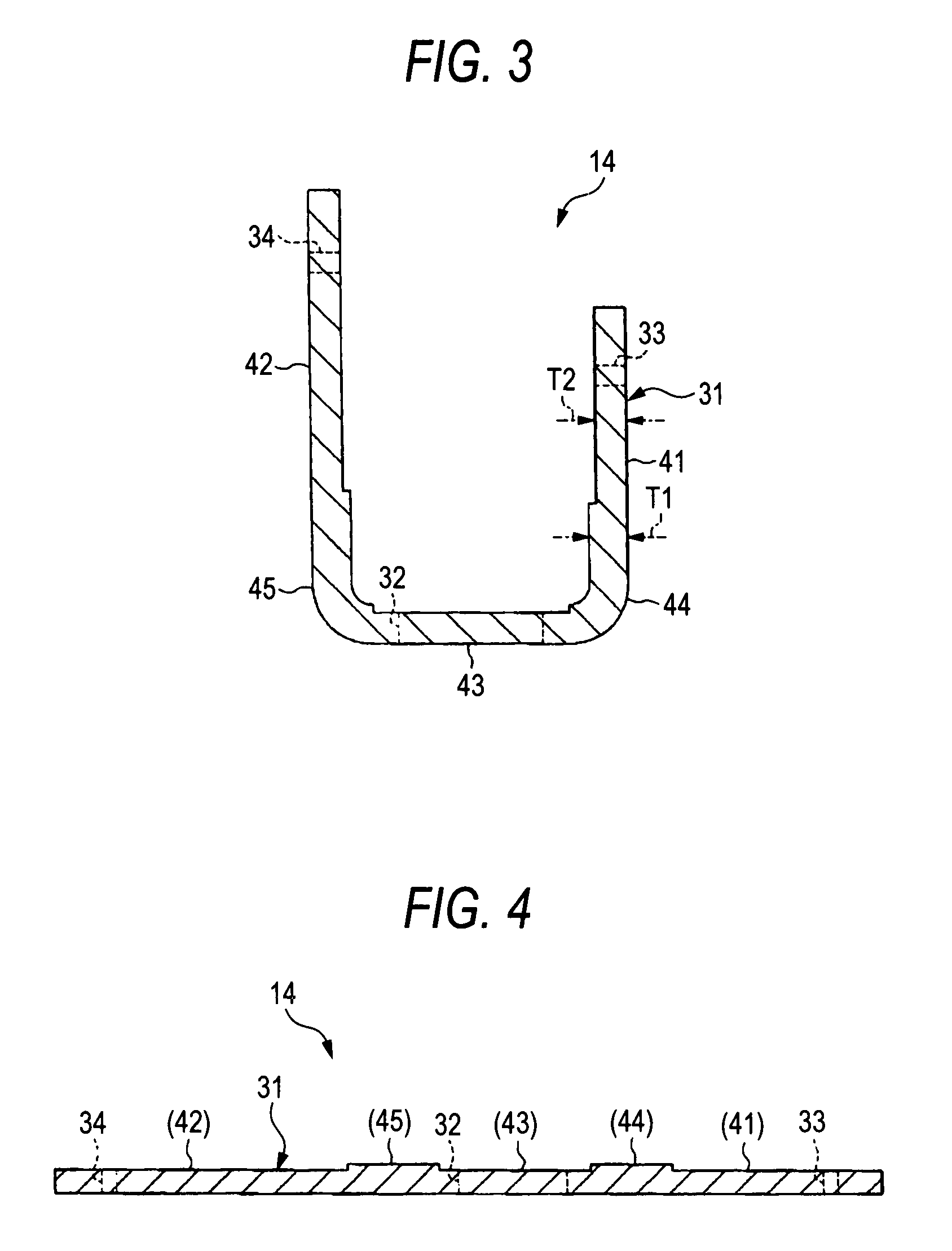
[0030]As shown in FIG. 1, the weather strip 4 has a trim portion 5 and a seal portion 6. The trim portion 5 has a vehicle interior side wall 11, a vehicle exterior side wall 12, and a curved-cross section connecting portion 13 connecting both the side walls 11 and 12. The trim portion 5 is substantially U-shaped in cross section, as a whole. The trim portion 5 is made of EPDM (ethylene-propylene-diene-copolymer) solid rubber. A metal insert 14 (in the present embodiment, the insert 14 is made of a cold rolle...


PUM

PropertyMeasurementUnit
thicknessaaaaaaaaaa
thicknessaaaaaaaaaa
thicknessaaaaaaaaaa

Abstract

A weather strip has a trim portion and a seal portion. The trim portion has a vehicle interior side wall, a vehicle exterior side wall, and a connecting portion. A metal insert is embedded in the trim portion. The insert has piece portions and a center bond portion which connects the piece portions to one another. The thickness of each of parts of the insert, which are other than both curved parts, is set to be thinner than the thickness of each of both the curved parts. Thus, the thickness of the insert, except for the curved parts, is small. Consequently, the entire insert, thus, the entire weather strip can be lightened. On the other hand, both the curved parts are relatively thick. Accordingly, the weather strip can assure predetermined strength and stiffness and can easily maintain an initial shape.

Description

BACKGROUND OF THE INVENTION[0001]1. Field of the Invention[0002]The present invention relates to a weather strip configured so that an insert is embedded in a trim portion.[0003]2. Related Art[0004]Generally, a weather strip having a trim portion is provided on a flange formed along the peripheral part of a door opening of a vehicle, such as an automobile. The weather strip has a trim portion, which has a holding lip held by being fit into the flange formed along the peripheral part of the door opening, and also has a hollow seal portion provided to protrude from the trim portion. The trim portion has a connecting portion, which connects a vehicle interior side wall, a vehicle exterior side wall, and both side walls, and is substantially-U-shaped in cross section.[0005]Also, a metal insert is embedded in the trim portion. As illustrated in FIG. 8, an insert 90 has a plurality of strip-like piece portions 91 disposed substantially parallel to one another and bond portions 92 (e.g., a...

Claims


Application Information

Patent Timeline
Patent Type & Authority Patents(United States)
IPC IPC(8): B32B3/02B32B3/26B60R13/06
CPCB60J10/0011B60J10/0031B60J10/08Y10T428/2495Y10T428/24198Y10T428/12389B60J10/18B60J10/24B60J10/80
Inventor IWASA, NORIMASAARITAKE, MASANORITOKI, SATOSHI
Owner TOYODA GOSEI CO LTD
Why Eureka
Try Eureka